Excertos do catálogo

RUGGED | COMPACT | LIGHTWEIGHT Version 4.1 − 08.2024 − Changes without prior notice High corrosion resistance
Abrir o catálogo na página 1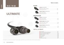
FISCHER ULTIMATETM SERIES PLUGS CABLE MOUNTED ■ ■ PANEL FRONT MOUNTED ■ ■ RECEPTACLES CABLE MOUNTED ■ ■ PANEL REAR MOUNTED ■ ■ PANEL FRONT MOUNTED ■ ■ This catalog covers our standard connector solutions. For specific requests, including hybrid or custom connectors, please contact your local sales representative. Technical Specifications
Abrir o catálogo na página 2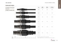
Size selection FISCHER ULTIMATETM SERIES AVAILABLE SIZES CONNECTOR SIZE VERSUS CABLE DIAMETER Min cable ø compatible with bend relief (accessory). Images of available sizes are on 1:1 scale when printed full size on A4 paper.
Abrir o catálogo na página 3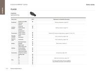
Body styles FISCHER ULTIMATETM SERIES PLUGS CABLE MOUNTED Body style Protection References to detailed information Sealing categories, page A-6 Friction Locking system Push-pull Quick-release Locking systems, page A-5 Lanyard Tamperproof Termination Housing material Crimp contact Solder contact Brass Aluminum Housing color Electrical & contact configurations, pages H-13 to H-18 Part numbering, page H-26 Part numbering, page H-26 Shortened body Body styles, chapter H Right-angle Cable clamp sets Cabling Overmoldable Heat shrinkable Cable bend reliefs Protective sleeves Sealing caps 07 08...
Abrir o catálogo na página 4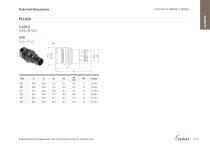
Technical dimensions FISCHER ULTIMATETM SERIES PLUGS CABLE MOUNTED UP01 BODY STYLE All dimensions and images shown are in millimeters and are for reference only.
Abrir o catálogo na página 5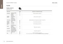
Body styles FISCHER ULTIMATETM SERIES PLUGS PANEL FRONT MOUNTED Body style Protection References to detailed information Sealing categories, page A-6 Friction Locking system Push-pull Quick-release Locking systems, page A-5 Lanyard Tamperproof Termination Housing material Housing color Crimp contact Solder contact Brass Aluminum Anthracite Electrical & contact configurations, pages H-13 and H-15 Part numbering, page H-26 Part numbering, page H-26 Shortened body Design Straight Right-angle Body styles, chapter H Front-mounting Rear-mounting Cable bend reliefs Protective sleeves Sealing caps...
Abrir o catálogo na página 6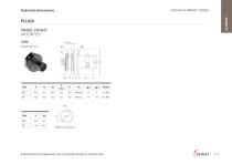
Technical dimensions FISCHER ULTIMATETM SERIES PLUGS PANEL FRONT MOUNTED UP50 BODY STYLE Panel cut-out PANEL CUT-OUT All dimensions and images shown are in millimeters and are for reference only.
Abrir o catálogo na página 7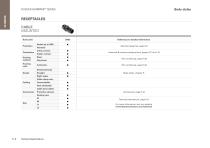
Body styles FISCHER ULTIMATETM SERIES RECEPTACLES CABLE MOUNTED Body style Protection Termination Housing material Housing color UR50 Sealed up to IP68 Hermetic Crimp contact Solder contact Brass Aluminum Anthracite References to detailed information Sealing categories, page A-6 Electrical & contact configurations, pages H-13 to H-16 Part numbering, page H-26 Part numbering, page H-26 Shortened body Design Body styles, chapter H Right-angle Cable clamp sets Cabling Overmoldable Heat shrinkable Cable bend reliefs Protective sleeves Sealing caps 07 Size Technical Specifications Technical...
Abrir o catálogo na página 8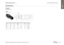
Technical dimensions FISCHER ULTIMATETM SERIES RECEPTACLES CABLE MOUNTED UR50 BODY STYLE All dimensions and images shown are in millimeters and are for reference only.
Abrir o catálogo na página 9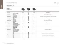
Body styles FISCHER ULTIMATETM SERIES RECEPTACLES PANEL MOUNTED Body style Protection References to detailed information Sealing categories, page A-6 Crimp contact Termination Solder contact Electrical & contact configurations, page H-13 to H-18 PCB contact Housing material Housing color Brass Aluminum Anthracite Part numbering, page H-26 Part numbering, page H-26 Right-angle Design Flush Front-projecting Bulkhead feedthrough Body styles, chapter H Front-mounting Rear-mounting Sealing caps Spacers Color-coded washers Grounding washers Locking washers 07 08 Size Technical Specifications...
Abrir o catálogo na página 10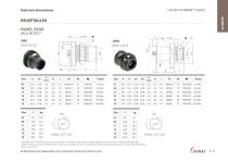
Technical dimensions FISCHER ULTIMATETM SERIES RECEPTACLES PANEL REAR MOUNTED* Panel cut-out BODY STYLE BODY STYLE Panel cut-out * Standard version with PCB contacts and grounding pin. For solder contact version, a special solder ground contact pin is included for AWG22[7/30]. 1) Solder & PCB ground pins are always equal or larger than the largest contact of corresponding contact bloc layout (except size 13 config. 203 AWG12 [7/20] ) 2) 3.6 mm for size 15 All dimensions and images shown are in millimeters and are for reference only
Abrir o catálogo na página 11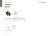
Technical dimensions FISCHER ULTIMATETM SERIES RECEPTACLES PANEL FRONT MOUNTED* UR03 2 BODY STYLE Technical Specifications Panel cut-out PANEL CUT-OUT * Standard version with solder contacts.
Abrir o catálogo na página 12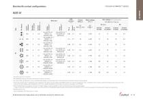
Electrical & contact configurations FISCHER ULTIMATETM SERIES Test voltage [kV] in mated position Layout reference Stranding values are in brackets. See dedicated crimping instructions document for further information. For a given AWG, the diameter of some stranded cable designs could be larger than the hole diameter of the barrel. Testing may be required. Current per contact at 40 °C temperature rise measured on the basic curve according to IEC 60512-5-2-5b. For maximum operating current, a reduction factor must be used and limitations due to the size of the wires and the permissible upper...
Abrir o catálogo na página 13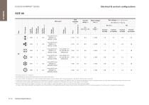
Electrical & contact configurations FISCHER ULTIMATETM SERIES Layout reference Test voltage [kV] in mated position Stranding values are in brackets. See dedicated crimping instructions document for further information. 3) For a given AWG, the diameter of some stranded cable designs could be larger than the hole diameter of the barrel. Testing may be required. 4) Current per contact at 40 °C temperature rise measured on the basic curve according to IEC 60512-5-2-5b. For maximum operating current, a reduction factor must be used and limitations due to the size of the wires and the permissible...
Abrir o catálogo na página 14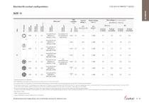
Electrical & contact configurations FISCHER ULTIMATETM SERIES Test voltage [kV] in mated position Layout reference Stranding values are in brackets. See dedicated wire gauge crimping instructions document for further information. 3) For a given AWG, the diameter of some stranded cable designs could be larger than the hole diameter of the barrel. Testing may be required. 4) Current per contact at 40 °C temperature rise measured on the basic curve according to IEC 60512-5-2-5b. For maximum operating current, a reduction factor must be used and limitations due to the size of the wires and the...
Abrir o catálogo na página 15Todos os catálogos e folhetos técnicos Fischer Connectors
-
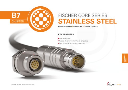
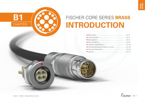 Fischer Core Series Brass
178 Páginas
-
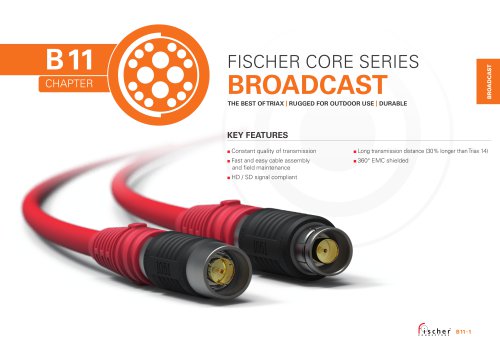 Fischer Core Series Broadcast
29 Páginas
-
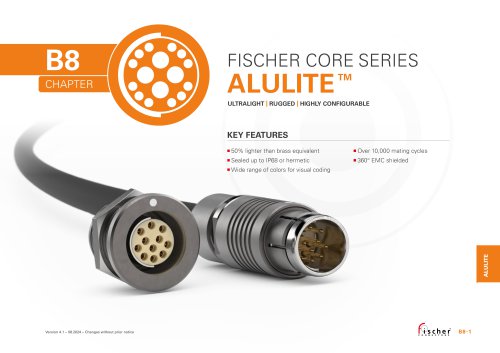 Fischer Core Series Alulite™
32 Páginas
-
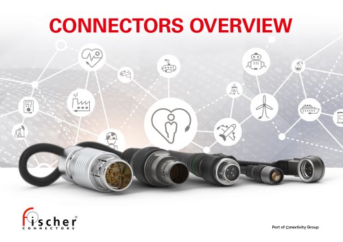 Connectors Overview
2 Páginas
-
 Cable Assembly Solutions
4 Páginas
-
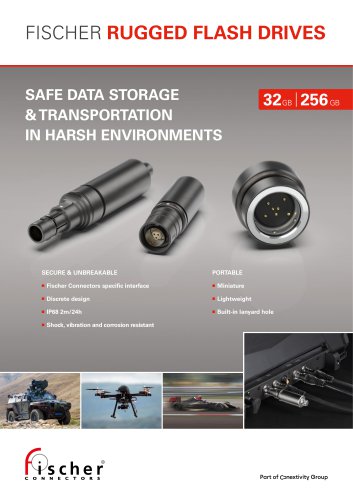 Fischer Rugged Flash Drives
4 Páginas
-
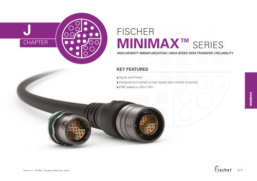 Fischer MiniMax™ Series
27 Páginas
-
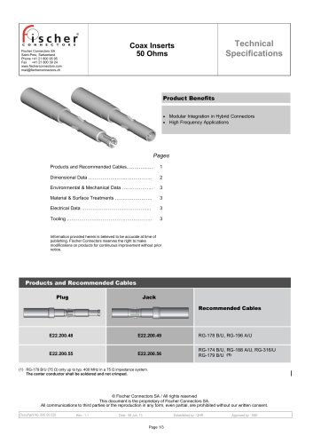 Coax Inserts 50 Ohms
3 Páginas
-
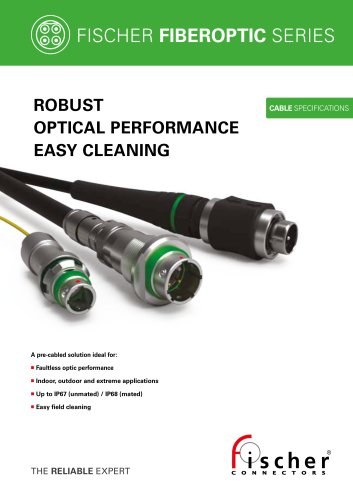
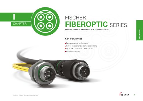 Fischer FiberOptic Series
32 Páginas
-
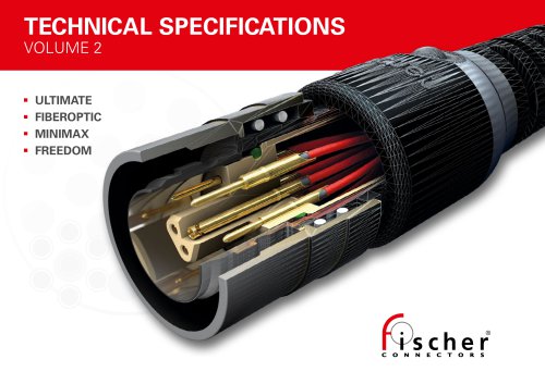 Technical Specifications Volume 2
148 Páginas
-
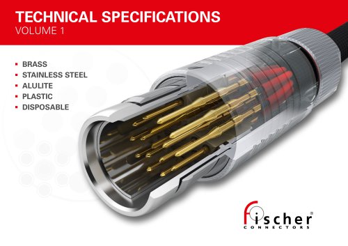 Technical Specifications Volume 1
293 Páginas