SCR100 Installation Guide

SCR100 Installation Guide
Catalog excerpts

! Warning: Don’t connect wires with power on! Installation Guide for SCR100 Device I. Install device III. Connect to door lock The device could connect to NC or NO locks, the connection terminal is not same, please according to the following diagram to make connection. 1)device and lock share power supply ALAL+ 1)Post the mounting template on the wall. Drill holes according to the marks on the template.(Holes for screw and wiring) 3) Take away the screw on the bottom of device Notice:If lock’s working power is DC12V, and working current is least 1000mA less than that of access control device power supply, wiring with sharing power supply can be adopted. 2)device and lock don’t share power supply + 5)Fix the cushion and plate on the wall 4) Release the mounting plate 6) Fix the device with the plate after all wiring completed II. Access control system overview BELL+ BELL- Notice: Wiring with lock power supplied independently is recommended for the following states: 1) Lock’s working power is DC 12V, device power’s current is not 1A more than that of lock. 2)Lock’s standard voltage is not DC12V. 3)The distance between lock and device is long. Access control system ① When a registered person verified, the access control device will export signal to open the door. ② Door sensor will detect on-off state to sense whether the door is opened by accident or the door is not closed well, alarm will be given off under abnormal condition. Card reader Release button ③If access control device is torn down illegally, or door sensor is abnormal, or menace alarm gives off, the device will export alarm signal. ④ Connect a Weigand reader to work as a controller. ⑤Access control device can be connected with external out-go switch, which provides convenience to open door from the inside. ⑥Access control software to manage multi devices via RS485 or TCP/IP. Ⅳ. Connection with other device + Alarm power Ⅴ.Power connection Release button BELLDoor sensor Notice: 1)The rating output of the alarm no more than DC12V. 2)The device has no bell button,so BELL+ and BELLterminals don’t work temporarily. The device’s working voltage is DC12V, with working current 500mA,standby current 50mA . Make sure the connection as th
Open the catalog to page 1
Ⅵ. Wiegand output connection Wiegand 26output interface, export the verified user number or card number to the controller. VII. Wiegand input connection Wiegand 26input interface to connect a Wiegand reader, the device works as a controller to verify the information sent from the wiegand reader. Reader and access control can be installed both inside and outside the door and control the lock and out & in together. ! Warning: Don’t connect wires with power on! 3、TCP/IP 1)Connection between device to PC via cross cable. Joint 1 TX+ TX RX+ RX - Notice: 1)The distance between device and access controller...
Open the catalog to page 2All ZKTeco catalogs and technical brochures
 QR600
QR6002 Pages
 ZPad Plus 4G
2 Pages
 TS1000 Pro (2025)
2 Pages
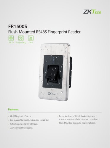 FR1500S (2025)
2 Pages
 CR20 Series (2025)
1 Page
Archived catalogs
 CR10
CR101 Page
 ZKIR372
2 Pages
 LH4000/LH5000
1 Page
 SLK20R
2 Pages
 Long Distance Wiegand Reader
2 Pages
 FBL2000 Series
2 Pages
 Biometric Flap Barrier
2 Pages
 SKW-V2/SKW-H2
2 Pages
 TS1000
2 Pages
 TS2000
2 Pages
 TS2100
2 Pages
 TS1200
2 Pages
 FBL2200 Series
2 Pages
 Biometric Tripod Turnstile
2 Pages
 MA300
MA3002 Pages
 TF1700
2 Pages
 F18
F182 Pages
 SC Series
2 Pages
 ZK4500
1 Page
 S400 / S500
2 Pages
 iClock680
2 Pages
 iClock-260 / 360
2 Pages
 iClock S900
2 Pages
 ZK-D1065S
2 Pages
 ZN-T1
ZN-T13 Pages
 ZN-TH01
1 Page
 ZL400
ZL4001 Page
 X8S
X8S1 Page
 MA300-BT
2 Pages
 SF420
SF4202 Pages
 FV350
FV3502 Pages
 KR 500 EL series
2 Pages
 SLK 20R
2 Pages
 SBT1000S Series
2 Pages
 FBL4200 Pro
2 Pages
 ZK-D100S
2 Pages
 series 44/45
2 Pages
 SCR100
2 Pages
 TS2200
2 Pages
 F18
F182 Pages


- KENNAMETAL aeronautic software
- KENNAMETAL real-time software
- Airport detector
- Tracking software
- KENNAMETAL fingerprint reader
- KENNAMETAL biometric fingerprint reader
- Airport turnstile
- USB fingerprint reader
- Server software
- Calculation software
- Walk-through detector
- Airport walk-through detector
- Geolocation software
- Airport access gate
- Access gate
- Standalone fingerprint reader
- Biometric software
- Access control card reader
- Airport card reader
- Windows software