
- Catalogs
- Vicor Corporation
- SOS028H3U800C001

SOS028H3U800C001

SOS028H3U800C001
- Compliance with Open VPX – VITA 62
- Input voltage range of 18 – 45V
- 800W output power
- Conduction cooling with I2C IPMI 46.11 monitoring and control
- Reverse-polarity protection and remote voltage sensing
- Parallel operation with wireless current sharing
- Protections against overcurrent, overvoltage, and overtemperature
- Military standard compliance (MIL-STD-704F, MIL-STD-461G, MIL-STD-810G, MIL-STD-1275E, RTCA/DO-160G)
- Total Output Power: 800W
- Operational Input Voltage: -0.5 to 100V
- Operating Temperature: -40 to 85°C
- Storage Temperature: -40 to 125°C
- Isolation Voltage: 500 VDC (IN to OUT and IN to CASE)
- Commands are recognized with the most-significant bit of each byte transmitted first.
- Command 0x21 provides sensor data, including PCBA temperature, voltage, and current readings.
- Commands 0x99 and 0x91 provide output and input current data in mA.
- Command 0x92 provides PCBA card edge temperatures.
- Allows monitoring of power supply readings and includes a battle override function to prevent shutdown during non-recoverable events.
- Bits indicate conditions such as battle override, fault conditions, and control priorities.
- Complies with VITA 46.11, VITA 62-2016, and IPMI v2.0 specifications.
- Sensor data is calculated using constants and equations to convert raw readings into real-world values.
- Upper and lower limits for sensors are defined, triggering system event messages when exceeded.
- Nonrecoverable limits cause shutdown, with auto-recovery attempts after 1s.
- Includes EMI filter, reverse voltage blocking, and isolated outputs for +3.3V and +12V.
- Internal power configuration detailed for VITA 3U P0 connector inputs.
- Dimensions and connector components specified, with part numbers for guide sockets and connector plugs.
- Version 1.1 includes corrections to connector pin descriptions, configuration options, and command contents.
Catalog excerpts

SOSA™ Aligned Power Supply SOS028x3U800yzzzSOSA-Aligned DC-DC Converter Features & Benefits • Open VPX - VITA 62 • 18 - 45V input voltage range • 800W output power • 3U Open VPX power supply • Conduction cooled • I2C IPMI 46.11 monitoring and control • Input voltage reverse-polarity protection • Remote voltage sensing for +12V and +3.3V auxiliary • Parallel operation capable with proprietary wireless current sharing • Overcurrent, overvoltage and overtemperature protections • IPC-A-610 class 3 • No aluminum electrolytic capacitors • Enable, inhibit, system reset and power fail controls • Meets military standard compliance: [a] ■ MIL-STD-704F ■ MIL-STD-461G ■ MIL-STD-810G ■ MIL-STD-1275E ■ RTCA/DO-160G Typical Applications • VPX power modules • Avionics • Shipborne electronics Product Description The Vicor SOSA-aligned power supply is a COTs power supply that is designed for 3U Open VPX systems that are developed to the SOSA standard. The module utilizes Vicor proprietary technology to enable high efficiency and power density for this highly rugged, conduction-cooled model. Up to four power supplies can be paralleled to increase output power capability of +12V main and +3.3V auxiliary outputs with proprietary wireless current sharing. Need for conventional current-share pins are eliminated. Current share accuracy is ±2A. Note: Product images may not highlight current product markings and cosmetic features. [a] See detailed specifications; contact Vicor Applications Engineering for report details. SOSA™ Aligned DC-DC Converter Page 1 of 26
Open the catalog to page 1
Note: See mechanical drawing on page 30 for connector information. SOSA™ Aligned DC-DC Converter Page 2 of 26
Open the catalog to page 2
SOSA™ Aligned DC-DC Converter Page 3 of 26 Rev 1.1 06/2023 VIGOR
Open the catalog to page 3
Part Ordering Information Specified Operating Area Figure 1 — Electrical specified operating area showing power limit de-rating
Open the catalog to page 4
All data at nominal line and nominal load unless otherwise specified.
Open the catalog to page 5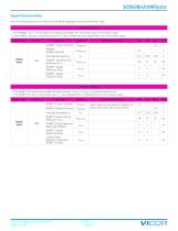
Signal Characteristics All of the following plots are at nominal line and 600W aggregate load unless otherwise noted. INHIBIT*: Inhibit* SOSA™ Aligned DC-DC Converter Page 6 of 26 Rev 1.1 06/2023 VIGOR
Open the catalog to page 6
All of the following plots are at nominal line and 600W aggregate load unless otherwise noted. • The GA0* and GA1* pins sets the I2C address of the power supply. Geographical address is set at start up and cannot be changed without a power cycle. • The GA0* and GA1* pins have an internal pull-up to VCC and is referenced to the Signal Return pin of the power supply.
Open the catalog to page 7
Figure 1 — Response time from VIN applied to outputs available; under 200ms start; VIN = 28V Figure 2 — VS1 (+12V) ripple at 10% load (6A), AC-coupled Figure 3 — AUX (+3.3V) ripple, AC-coupled SOSA™ Aligned DC-DC Converter Page 8 of 26
Open the catalog to page 8
General Characteristics SOSA™ Aligned DC-DC Converter Page 9 of 26 Rev 1.1 06/2023 VIGOR
Open the catalog to page 9
Table 1 — ENABLE & INHIBIT logic Table 2 — Geographical address assignment Signal Pin Functions ENABLE* & INHIBIT* Enable and Inhibit pins express active low logic. Table 1 has the truth table for the output state of the power supply. It is necessary to avoid the indeterminate output state where 0.8 - 2.0V is applied to the ENABLE* or INHIBIT* pins. A digital debounce filter is present on the signals of both pins to prevent false transitions. The ENABLE* and INHIBIT* also have a minimum delay between successive output enable transitions to prevent repeated starts into high capacitance loads....
Open the catalog to page 10
SOS028x3U800yzzz Card Edge Temperature Sensors Fault Operation The PCBA card edge temperature sensor internal to the power supply is mounted on the edge of the PCBA card edge. Consequently, the temperature sensor measures a temperature that is generally higher than the heat-sink-to-rail mounting interface and lower than the hot spot of the internal converters in the power supply. See Table 5 for nonrecoverable fault thresholds which trigger a fault and shut down/restart of the outputs of the supply. Response from the power supply to I2C command 0x21 provides the temperature measured by the internal...
Open the catalog to page 11
Parallel Operation For proper load regulation and paralleling of like power supplies, a single kelvin connection between each sense pin and load is required. Under normal parallel power supply operation, each supply's PoL regulated output will be at different voltage with respect to its own backplane connector to compensate for transmission voltage drop. Figure 5a depicts an instance of a backplane with three power supplies where the point-of-load (PoL) sense pins on each power supply are connected. It is not recommended to connect the PoL sense pins in a manner depicted in Figure 5b where each...
Open the catalog to page 12
Table 4 — Byte sequence to set the power supply in standalone Standalone Operation Switching the power supply from paralleling to standalone can be done on a single-use basis or permanently by the user using I2C. Each unit ships from the factory capable of paralleling multiple identical power supplies. If the power supply is used in standalone mode without additional identical supplies connected in parallel, the output voltages of the power supply that are shareable, namely, VS1 and VAUX, will not droop with increased current load and will regulate the output voltage close to the no-load voltage....
Open the catalog to page 13
SOS028x3U800yzzz Conducted Emissions Testing CE102, Conducted Emissions, Power Leads Limit Level Line Under Test: Positive 28VDC Input EUT Mode: EUT Loaded Line 1 Measured Emissions Ambient Scan Measured Value Amplitude (dBµV) Figure 6 — Conducted emissions of +28V input line at full load CE102, Conducted Emissions, Power Leads Limit Level Line Under Test: Return Input EUT Mode: EUT Loaded Line 2 Measured Emissions Ambient Scan Measured Value Amplitude (dBµV) Figure 7 — Conducted emissions of +28V return line at full load SOSA™ Aligned DC-DC Converter Page 14 of 26
Open the catalog to page 14All Vicor Corporation catalogs and technical brochures
 VITA 62 Power Supply
31 Pages
 VITA 62 Power Supply
34 Pages
 DCM™ DC-DC Converter
32 Pages
 SOSA™ Aligned Power Supply
26 Pages
 SOS028H3U600D001
26 Pages
 SOS028H3U800C000
26 Pages
 SOS028H3U800D000
26 Pages
 SOS028H3U800D001
26 Pages