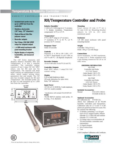
Four Channel MEMS Engine Driver Amplifier
Four Channel MEMS Engine Driver Amplifier
The document provides technical specifications and operational details for the Model 2375 MEMS Amplifier, designed for use with the TEGAM 9070 MEMS Engine Driver System. It is suitable for applications requiring precise signal amplification of unipolar or DC biased AC waveforms.
Specifications
- Electrical: The amplifier has four channels with an input impedance of 10 kΩ and an output voltage range of 0 to +150 VDC in splitter mode and -7 to +150 VDC in splitter bypass mode. It supports a maximum output current of 20 mA per channel and has an output impedance of less than 0.2 Ω. The voltage gain is fixed at +15, with a full power bandwidth of 5 kHz.
- Performance: The amplifier can handle capacitive loads up to 200 pF while maintaining a full power bandwidth exceeding 5 kHz. It features a slew rate of over 5 V/μSec and a square wave response of less than 25 μSec for a 150 Volt step.
- Environmental: Operating temperature ranges from 0 ºC to +45 ºC, with a storage temperature range of -20 ºC to +50 ºC. The humidity range is 80% RH non-condensing.
- General: The input supply voltage is 110/220 50/60 Hz, with a power rating of 100 VA; 80 W. The dimensions are 11.5 x 25.8 x 30.0 cm, and the weight is approximately 4.5 kg. The warranty covers 1 year for parts and labor.
Operational Modes
The Model 2375 operates in two modes: normal (splitter bypass) mode and splitter mode. In normal mode, each input signal is amplified by a factor of 15. In splitter mode, the signal splitter rectifies a bipolar input signal into waveforms for MEMS micro engine actuators.
Applications
The amplifier is specifically designed for MEMS engine drivers but can be used for other applications requiring precise signal amplification. It is compatible with standard arbitrary waveform or function generators.
Figures and Diagrams
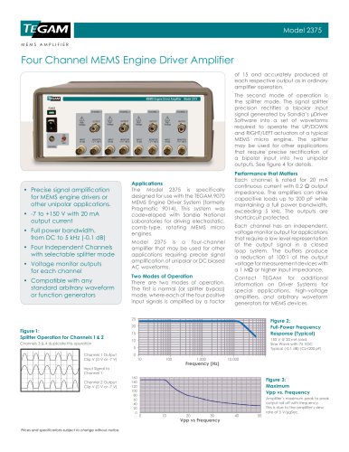
- Figure 1: Illustrates the splitter operation for channels 1 & 2, with channels 3 & 4 duplicating this operation.
- Figure 2: Shows the full-power frequency response, indicating the amplifier's performance across different frequencies.
- Figure 3: Depicts the maximum Vpp vs. frequency, highlighting the amplifier's peak-to-peak output roll-off with frequency.
- Figure 4: Provides an operational diagram of the Model 2375, showcasing its application in high-voltage driver amplifiers for MEMS engines.
Contact Information
For additional information, contact TEGAM at their Geneva, Ohio location, or visit their website.
Catalog excerpts

Model 2375 MEMS AMPLIFIER Four Channel MEMS Engine Driver Amplifier of 15 and accurately produced at each respective output as in ordinary amplifier operation. The second mode of operation is the splitter mode. The signal splitter precision rectifies a bipolar input signal generated by Sandia’s µDriver Software into a set of waveforms required to operate the UP/DOWN and RIGHT/LEFT actuators of a typical MEMS micro engine. The splitter may be used for other applications that require precise rectification of a bipolar input into two unipolar outputs. See figure 4 for details. • recise signal amplification P for MEMS engine drivers or other unipolar applications. • 7 to +150 V with 20 mA output current • ull power bandwidth, F from DC to 5 kHz (-0.1 dB) • our Independent Channels F with selectable splitter mode • oltage monitor outputs V for each channel • ompatible with any C standard arbitrary waveform or function generators Applications The Model 2375 is specifically designed for use with the TEGAM 9070 MEMS Engine Driver System (formerly Pragmatic 9014). This system was codeveloped with Sandia National Laboratories for driving electrostatic, comb-type, rotating MEMS micro engines. Model 2375 is a four-channel amplifier that may be used for other applications requiring precise signal amplification of unipolar or DC biased AC waveforms. Two Modes of Operation There are two modes of operation. The first is normal (or splitter bypass) mode, where each of the four positive input signals is amplified by a factor Performance that Matters Each channel is rated for 20 mA continuous current with 0.2 Ω output impedance. The amplifiers can drive capacitive loads up to 200 pF while maintaining a full power bandwidth, exceeding 5 kHz. The outputs are shortcircuit protected. Each channel has an independent, voltage monitor output for applications that require a low level representation of the output signal in a closed loop system. The buffers produce a reduction of 100:1 of the output voltage for measurement devices with a 1 MΩ or higher input impedance. Contact TEGAM for additional information on Driver Systems for special applications, high-voltage amplifiers, and arbitrary waveform generators for MEMS devices. Figure 1: Splitter Operation for Channels 1 & 2 Channels 3 & 4 duplicate this operation Channel 1 Output Clip V (0 V or -7 V) Input Signal to Channel 1 Channel 2 Output Clip V (0 V or -7 V) Figure 2: Full-Power Frequency Response (Typical) 150 V @ 20 mA load. Sine Wave with 75 VDC Typical (-0.1 dB) (CL<200 pF) Figure 3: Maximum Vpp vs. Frequency Prices and specifications subject to change without notice. Amplifier’s maximum peak to peak output roll off with frequency. This is due to the amplifier’s slew
Open the catalog to page 1
MEMS AMPLIFIER Model 2375 Specifications Electrical Number of Channels Input Impedance Output Voltage Range Maximum Output Current Output Impedance Voltage Gain Sine Wave Distortion (THD) Full Power Bandwidth Slew Rate Square Wave Response Aberrations Voltage Monitor Outputs Environmental Operating Temperature Storage Temperature Humidity Range General Input Supply Voltage Power Rating Dimensions: (H x W x L) Weight (approximate) Warranty Included Accessories Optional Accessories 4 10 kQ 0 to +150 VDC (Splitter Mode) -7 to +150 VDC (Splitter Bypass Mode) 20 mA per channel < 0.2 Q +15 Fixed <...
Open the catalog to page 2All Tegam catalogs and technical brochures
 Decade Ratio Transformer
2 Pages
 R1L-E2A
2 Pages
 R1L-D1
2 Pages