- Catalogs
- Strulik GmbH
- Fire Prevention Part III
Fire Prevention Part III

Fire Prevention Part III
This document provides comprehensive guidelines and specifications for smoke exhaust systems, focusing on both natural and mechanical smoke extraction methods. It includes detailed descriptions of system components, installation guidelines, and operational procedures.
- Smoke Control Dampers: Various types of dampers, including RKU-90, RKI-90, and RKE models, are discussed with specific fire resistance classes and functional endurance times. These dampers are crucial for maintaining safety by controlling smoke extraction and preventing fire spread.
- Smoke Extraction Ducts: Specifications for ducts made of sheet steel, capable of withstanding high temperatures (up to 600°C for 120 minutes), are provided. These ducts are essential for effective smoke extraction in fire zones.
- Compensators: WSK compensators are highlighted for their ability to withstand temperature changes up to 1000°C, ensuring system integrity under extreme conditions.
- Installation guidelines emphasize the integration of smoke exhaust systems with fire detection systems and building automation to ensure timely activation during a fire.
- Regular maintenance and functional testing are recommended to ensure system reliability, with specific intervals outlined for different components.
- Actuating and Evaluating Units: These units control smoke control dampers and ventilators, ensuring automatic operation upon smoke detection. They include features for manual override and fault indication.
- Power Supply: A reliable power supply is critical, with recommendations for alternative power sources to ensure system functionality during a fire.
The document classifies smoke control dampers based on their application in different fire zones and outlines the requirements for their construction and operation, including fire resistance times and leakage limits.
This document serves as a technical guide for the design, installation, and maintenance of smoke exhaust systems, emphasizing safety and compliance with relevant standards.
- Smoke Detectors: Operate using the Tyndall effect, with a working voltage of 16-30 V DC and a current of approximately 0.04 mA. They feature a service alarm at 70% soiling and require manual reset after an alarm.
- Smoke Control Dampers: RKU-90 model with a fire resistance time of 90 minutes, made from calcium silicate boards, and available in various dimensions. They are designed for installation in solid and lightweight walls.
- Control Units: EKS control units for smoke exhaust systems, with IP 65 safety rating, operating at 230 V ± 10% and 50-60 Hz frequency.
- Smoke detectors should be installed on ceilings, with coverage of 60 m² for rooms up to 6 m high, and 80 m² for taller rooms.
- Smoke control dampers can be installed in solid walls, lightweight constructions, and directly onto concrete walls, with specific guidelines for gap filling and mounting positions.
- Minimum distances and specific materials (e.g., mineral wool, mortar) are required for proper installation and fire safety compliance.
- Smoke detectors emit a red LED alarm signal when smoke is detected, requiring manual reset.
- Control units feature LEDs for operational status, smoke alarms, and collective faults, with manual and automatic operation modes for smoke control dampers and ventilators.
- All components and procedures comply with relevant standards such as EN-54/7 and DIN regulations, ensuring safety and reliability in smoke control systems.
- Installation and operational guidelines are designed to meet fire safety requirements and enhance the effectiveness of smoke management in buildings.
The RKU-90 smoke control damper is designed for fire safety with a resistance class of EK90 and a fire resistance time of 90 minutes. It is suitable for installation in various wall types, including brickwork and concrete, and can be mounted in different positions.
- Angle brackets and U-traverses are required for specific dimensions.
- Components include zinc-plated steel brackets, CARBOWOOL sealing, hexagon head screws, washers, and fire safety dowels.
- Intumescent material is used to compensate for linear expansion during fire exposure.
- Smoke control dampers require specific mounting hardware, including suspension angles and threaded rods.
- Provisions for connecting with smoke extraction ducts are detailed, including compensators and duct specifications.
- Suspension and dimensioning guidelines are provided, with references to DIN standards.
- Motors such as BE24, BE230, SEL 2.90, and SEL 1.90 are used, with specific wiring and control requirements.
- Noise levels, pressure differences, and acoustic power are calculated based on given dimensions and flow rates.
- Detailed weight specifications for various damper sizes and components are provided.
- Load capacities for threaded rods and dowels are specified, ensuring compliance with safety standards.
- All installations must comply with relevant test certificates and standards.
- Maintenance-free motors and specific wiring diagrams are available upon request.
This document provides technical specifications and installation guidelines for smoke control dampers, specifically the RKU-90 and RKI-90 models, used in smoke exhaust systems and ventilation modes. It includes details on control mechanisms, fire resistance, and installation requirements.
- RKU-90-KL: Designed for smoke exhaust systems with a fire resistance class of EK90 and a fire resistance time of 90 minutes. It includes an electric actuating drive with an energy storage system to ensure closure during power failures.
- RKI-90: Features a multi-blade damper design with a fire resistance class of EK90. It is suitable for installation in smoke extraction ducts with a fire resistance time of 90 minutes.
- Both models utilize an SLC technique (two-wire control) for power supply and control, requiring specific communication modules.
- The RKU-90-KL model includes a backup accumulator to maintain functionality during power interruptions.
- Smoke control dampers can be installed in various positions, including walls, floors, and ducts, with specific requirements for each setup.
- Installation examples and dimensions are provided for different configurations, emphasizing the importance of proper sealing and support structures.
- Smoke control dampers must meet fire safety standards and have the endurance to extract hot flue gases.
- They should be equipped with reversible drives to maintain open or closed positions as needed, without relying on fusible links or spring returns.
- Design diagrams and conversion factors are provided to assist in calculating pressure loss and noise levels based on volume flow rates.
- Specific correction factors are outlined for different fitting positions to ensure accurate performance assessments.
Specifications
The RKI-90 smoke control damper is designed for use within smoke extraction ducts with a fire resistance class of EK90, capable of withstanding fire for 90 minutes. It features a housing and lamella made from asbestos-free fireproofing boards, with a stainless steel damper blade axis supported in bronze sleeves.
- Nominal voltage options: 24 V or 230 V
- Power consumption varies by model, with SEL 2.90 consuming 12 W in operation and SEL 1.90 consuming 8 W.
- Torque: Minimum 40 Nm
- Running time: Less than 60 seconds
- Noise level: Maximum 62 dB(A)
- Rotation angle: 100° for SEL 2.90 and 93° for SEL 1.90
- Maintenance-free operation
The damper is suspended using threaded rods, with specific requirements for the load and dimensions to ensure safety and compliance with fire resistance standards. The rods must be covered if the suspension height exceeds 1.5 meters.
The motors are controlled via two-point or two-wire techniques, with specific wiring diagrams provided. The SEL 1.90 SLC motor requires a two-wire technique and can be connected via safety communication modules.
All installations must adhere to VDE guidelines, and the use of fire safety dowels is specified for secure suspension. The dowels must comply with European test certificates.
The RKI-90-KL variant includes an additional energy storage system to ensure closure during power failures, enhancing fire safety. It is controlled via the SLC-BUS system.
Dimensions and motor types must be specified when ordering, with options for additional accessories like communication devices for SLC technique.
The document provides technical specifications, installation guidelines, and performance data for the RKE smoke control dampers, certified under test certificate Z-78.2-47. These dampers are designed for functional endurance of 60 minutes at 600°C or 120 minutes at 400°C.
The smoke control dampers are constructed with galvanized steel housing and asbestos-free fireproofing boards. They are equipped with stainless steel damper blade axes supported in bronze sleeves. The dampers are controlled via electric actuating drives, available in 24 V or 230 V configurations, with options for two-point or SLC technique control.
The document includes diagrams for determining total pressure loss and noise levels based on volume flow rates. Correction factors are provided for different fitting positions such as duct connections and free blowout/suction scenarios. The dampers are designed to be maintenance-free and have a noise level of up to 62 dB(A).
The motors (BE24, BE230, SEL 2.90, SEL 1.90) have specific power consumption and torque ratings. The SEL 1.90 SLC motor uses a two-wire technique for control and requires additional communication modules for data reception.
The document outlines the use of fire safety dowels and threaded rods for suspension, adhering to DIN standards. The dampers must be installed with appropriate steel dowels and compensators to manage duct elongations and horizontal forces.
The WSK-600 compensator is detailed, designed for installation in smoke extraction ducts, with a functional endurance of 120 minutes at 600°C. It is constructed with spun glass fabrics and elastomer coating, intended to balance duct elongations.
The document provides ordering examples and dimensions for both the RKE dampers and WSK-600 compensators, emphasizing the need for precise measurements and adherence to installation guidelines.
The document provides technical specifications and installation guidelines for smoke extraction ducts and compensators made of sheet steel, designed for use within a single fire zone. These components are tested for functional endurance at 600°C for 120 minutes.
- The WSK-R-600 compensator is intended for round sheet metal smoke extraction ducts, with a required installation dimension of 155 ± 2 mm between ducts.
- Compensators should be arranged between walls for horizontal ducts longer than 5 meters, with a maximum distance of 10 meters between compensators.
- Smoke extraction ducts are made from galvanized sheet steel, with dimensions ranging from NW 100 to 1000 mm, and are delivered as a complete system with mounting accessories.
- Tested in accordance with DIN 18232-6 and prEN 1366-9 standards, ensuring endurance at 600°C for 120 minutes.
- Pressure levels are specified for both overpressure and underpressure conditions, with leakage not exceeding 3.75 m³/h per m² at -1500 Pa underpressure.
- Smoke extraction ducts should not pass through fire-resistant walls into other compartments.
- Non-combustible sealings and M8 screws are used for connecting duct pieces, with specific guidelines for suspension using L-profiles or C-profiles.
- Vertical deviations and inclined ducts have specific installation requirements to ensure stability and safety.
- Manufactured by Strulik GmbH, the ducts and compensators are delivered with necessary accessories like clamping collars, fire safety dowels, and threaded rods.
- Round smoke extraction ducts are available in standard lengths of 3 m and 6 m, with diameters ranging from 100 mm to 1000 mm.
- Design of bends and tee fittings follows specific guidelines, with allowances for vertical deviations up to 2500 mm.
- Smoke extraction ducts meet class C leakage requirements as per DIN EN 12237.
The document outlines the specifications for compensators and smoke extraction ducts. The compensators are tested according to DIN 18232-6 and can withstand temperatures up to 1000°C. The compensator's material build-up includes layers of stainless steel wire gauze, silicate gauze, glass fibre, and stainless steel foil.
Installation procedures for compensators and smoke extraction ducts are detailed. The compensators should be installed between smoke extraction ducts or directly connected to smoke control dampers. The document specifies the use of M8 screw bolts and provides guidelines for the installation of vertical shafts using WAKOFIX-LS L90 shafts.
The document references several standards, including DIN 18232 and DIN 4102, for testing fire resistance and construction principles. The WAKOFIX-LS L90 and WAKOFIX-F L90 shafts are tested for fire resistance in the L90 class.
Recommendations include maintaining a distance of ≤ 3 m for wall fixing arrangements and ensuring proper load distribution when shafts penetrate floors. The document also advises on the use of supporting constructions for vertical shafts.
The tables provide detailed descriptions of items such as compensators and fireproof shafts, including unit prices and total costs. The material specifications, dimensions, and installation methods are also outlined.
The document provides contact details for Strulik GmbH and its international partners across various countries, including Germany, Austria, France, Hungary, Ireland, Iceland, Italy, Netherlands, Poland, Switzerland, Turkey, and the United Kingdom.
Catalog excerpts

Fire Prevention Smoke exhaust systems Part III – 03/2007 1000 Standard time temp. curve Temperature increase inside the furnace 20 25 30 40 50 60 70 open/close Time since the start of the test [min]
Open the catalog to page 1
Contents illustrated in photos Smoke exhaust systems System differences / installation guidelines Classification and requirements for smoke control dampers Control of smoke exhaust systems and planning guidelines for smoke detectors RKU-90/Z-78.2-12 smoke control damper RKU-90-KL/Z-78.3-78 smoke control damper for the additional usage in ventilation mode RKI-90/ Z-78.2-11 smoke control damper RKI-90-KL smoke control damper for the additional usage in ventilation mode RKE/Z-78.2-47 smoke control damper RKE-KL smoke control damper for the additional usage in ventilation mode Smoke extraction duct...
Open the catalog to page 2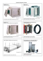
Contents illustrated in photos RKU-90/Z-78.2-12 RKU-90-KL/Z-78.3-78 See page 10 to 31 Fire resistance class EK-90/fire resistance time of 90 min. Functional endurance of 60 min. at 600 °C or 120 min. at 400 °C within smoke extraction ducts of sheet steel RKI-90/Z-78.2-11 RKI-90-KL ( the test certificate has been applied for) Fire resistance class EK-90 within smoke extraction ducts with a fire resistance time of 90 min. Functional endurance of 120 min. at 600 °C within smoke extraction ducts of sheet steel L90/P-TUM-405/P-TUM-406 smoke extraction duct Smoke extraction duct of sheet steel/P-TUM-411...
Open the catalog to page 3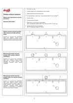
Natural and mechanical smoke extraction General information Smoke exhaust zone, separated by smoke curtains Natural smoke and heat exhaust vent Air inlet opening or wake max. 3 m/s (recommended 1,5 m/s) (symbol ) Smoke curtain Smoke exhaust ventilator RKE smoke control damper (uninsulated) 400 °C temperature stress at 400 °C for 120 min. or 600 °C for 60 min. Smoke exhaust systems Fire zone, e.g. hall Smoke extraction duct (uninsulated) 600 °C temperature stress for 120 min. Natural smoke exhaust system with smoke and heat exhaust vents Drawing of a common fire compartment (hall) with different...
Open the catalog to page 4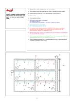
Smoke exhaust system example with several fire zones lying one upon the other or next to each 1 Separate fire or smoke exhaust zones, e.g. halls or stores 2 Smoke exhaust zones within separated fire zones or separated by smoke curtains 4* Air inlet opening or wake max. 3 m/s (recommended 1,5 m/s) (symbol *) 6 Smoke exhaust ventilator 7 RKE smoke control damper (uninsulated) 8 Smoke extraction duct (uninsulated) 9 Fire resistant smoke extraction duct (e.g. WAKOFIX-F L90), tested in accordance with DIN 4102-4 and DIN 18232-6 (pre-standard) with fire resistance class L90 (test temperature: standard...
Open the catalog to page 5
The test certificate requires that smoke control dampers are only used for the extraction of smoke by means of smoke exhaust systems and for the inlet of supply air for smoke exhaust systems. System differences Smoke exhaust systems In principle, smoke control dampers are fitted with electric motors that are L90-enclosed. The specified manual release for opening and closing the smoke control damper within the scenario shall be guaranteed by a manual switch (by the installer). The smoke control damper motors, smoke detectors and smoke control dampers are connected to the controller, as described...
Open the catalog to page 6
Requirements for smoke control dampers, tested in accordance with the principles of testing (edition July 1998), pursuant to DIN 18232-6 (pre-standard of October 1997) and fire resistance time of 90 min. in accordance with DIN 4102-6. Classification and requirements of smoke control dampers with test certificate Classification of smoke control dampers for mechanical smoke extraction There are three different types: General The components of smoke control dampers shall essentially consist of class A building materials in accordance with DIN 4102-1 The clear dimensions of smoke control dampers...
Open the catalog to page 7
Actuating and evaluating unit Optical smoke detector Manual alarm box Actuating and evaluating unit Optical smoke detector with service alarm Type: ST-P-DA-STB EKS actuating and evaluating unit 24 V– and smoke exhaust ventilators with a working voltage of 230 V– and 400 V– (separate power element). The smoke detector signals the following: For the control of smoke exhaust ventilators and smoke control dampers with test certificate for individual or several smoke zones and fire compartments. The EKS activating and evaluating unit shall reliably and immediately put the smoke exhaust systems or...
Open the catalog to page 8
The drawings (example) suits EKS for two smoke control dampers EKS control for smoke exhaust systems Activating and evaluating unit Basic unit, one smoke zone, two smoke control dampers Individual planning according to the construction and function of the smoke exhaust system on request. EKS allocation scheme (example) Manual alarm box Yellow Manual switch CLOSED OPEN S centre Smoke detector Technical data Smoke detector suppy Wall housing of sheet steel Cable lead: Via bolted PG joint with traction relief, optionally at the top or at the bottom Another smoke detector Damper drive 1 Damper drive...
Open the catalog to page 9
Technical data Functioning principle: Optical smoke detector with service alarm Type: ST-P-DA-STB Please note: Only to be used in combination with the EKS (SLC) Scattered light (Tyndall effect) Test as in EN-54/7: LPCB (Great Britain) Smoke signal part: VdS G298064 Working voltage: 16 – 30 V DC Working current: ca. 0,04 mA Service alarm current: ca. 13 mA Alarm current: ca. 55 mA Operating temperature: -10 °C to +50 °C Maximum humidity: 99 % rF Detector housing: White polycarbonate with a grille against insects Base: White polycarbonate Weight: ca. 180 kg Service alarm display: Green LED Smoke...
Open the catalog to page 10
Manual alarm box monitored for cable break and short circuit Type: DKM Technical data The control of mechanical smoke ventilation systems with/without smoke control dampers »Smoke control damper open« »Smoke exhaust ventilator on« Button unlocked: Button pressed: Length = 125 mm Width = 125 mm Height = 34 mm Green LED »operating lamp« Red LED »smoke alarm« Yellow LED »collective fault« Working voltage: Unblocking potential: 24 V AC/DC Current on contact: Releasing resistance: 1,5 kΩ Terminal resistance: 1 kΩ Terminal S1: Cable inlet at the top M 20 x 1,5 and at the bottom: Installation: Surface...
Open the catalog to page 11All Strulik GmbH catalogs and technical brochures
 BEK
BEK15 Pages
 BCF-K90
16 Pages
 BCF-2-K90
19 Pages
 Fire Prevention Part V
22 Pages
 Fire Prevention Part II
61 Pages
 Fire Prevention Part I
213 Pages