- Catalogs
- Strulik GmbH
- Fire Prevention Part II
Fire Prevention Part II

Fire Prevention Part II
This document outlines the technical specifications and installation guidelines for fire prevention dampers and systems, adhering to DIN 18017-3 standards. It covers damper types, installation procedures, and compliance with fire safety standards.
The document compares K90-18017-3 and K90-4102-6 dampers, focusing on fireproofing capabilities and testing methods. K90-18017 dampers are designed for ventilation ducts with stricter temperature resistance and release mechanisms.
Specifications for damper models WBE, WBV, WBZ, and BSE are detailed, including installation guidelines for walls and floors. Key specifications include maximum connection size and temperature increase limits.
Testing arrangements for K90 and K90-18017 dampers are described, highlighting differences in temperature exposure and test conditions.
Instructions for wet and dry installations are provided, emphasizing compliance with fire safety standards.
Features of WBE dampers include resistance class K90-18017, low noise levels, and compatibility with various duct sizes.
The document emphasizes the importance of adhering to guidelines and standards for effective fire prevention systems.
Details on dampers with hermetically enclosed release mechanisms, including test certificates and resistance class K90-18017, are provided.
Installation procedures for wall and floor applications are outlined, stressing the importance of following guidelines and maintenance instructions.
Dampers comply with DIN 18017 and are tested according to IEC and EN standards, suitable for domestic kitchens.
Optimal airflow velocity should not exceed 8 m/s, and dampers are designed to minimize noise while maintaining air volume control.
Includes dimensions, pressure loss, noise level, and mounting frame details, with diagrams for air control and noise adjustments.
Includes electrical limit switches and special mounting frames for specific installation requirements.
Technical specifications and installation guidelines for Strulik dampers, specifically WBV and BSE series, are provided, suitable for fire-resistant ventilation systems.
Details on damper types, resistance class, activation temperature, and material are included.
Dampers can be installed in walls and floors, with various mounting frames available.
Dampers feature a hermetically enclosed release mechanism, ensuring fire protection and low noise levels.
Dampers should be serviced regularly, with testing to ensure correct operation.
High resistance to fire and smoke, suitable for domestic kitchens and central ventilation systems.
Technical specifications and installation guidelines for BSV and BZV models are provided, suitable for fire-resistant ventilation systems.
Details on damper sizes, construction material, and activation mechanism are included.
Dampers can be installed inside or outside walls, with various mounting frames available.
Regular servicing and inspection are required, using original parts for repairs.
Dampers provide low noise levels and efficient air volume control, complying with DIN 18017.
Combines air ducts with MF dampers, suitable for residential ventilation, meeting noise protection requirements.
Details on ventilation systems and components, including materials and dimensions, are provided.
Assembly instructions for ducts with fire resistance classes are described.
Multiple test certificates and resistance classes ensure compliance with fire safety standards.
Specific dampers and ducts are recommended for different systems, with fireproofing elements advised for safety.
Tables compare system differences, providing dimensions and safety compliance details.
Ensuring ducts meet fire resistance classes and using appropriate materials are emphasized.
Technical specifications and installation guidelines for fire safety and ventilation systems, focusing on the D.A.S. fire safety system, are provided.
Systems are designed according to DIN 18017-3, with key components and test certificates ensuring resistance class K90-18017 S.
Details on installation using steel rivets, mounting frames, and fireproof adhesives are provided.
Various components and accessories are listed, ensuring compatibility and ease of installation.
Sound-absorbing bends are recommended for noise protection, with specific mounting frames advised for system integrity.
Contact details for Strulik GmbH and international partners are provided for support and additional information.
Catalog excerpts
Fire Prevention Dampers and system solutions in accordance with DIN 18017-3 Part II – 01/2006 »System solutions«
Open the catalog to page 1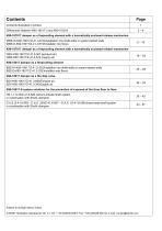
Contents illustrated in photos Differences between K90-18017-3 and K90-4102-6 K90-187017 damper as a fireproofing element with a hermetically enclosed release mechanism WBE-W-K90-18017/Z-41.3-619/Installation into shaft walls or system-tested walls WBE-D-K90-18017/Z-41.3-619/Installatin into floors K90-187017 damper as a fireproofing element with a hermetically enclosed release mechanism WBV-K90-18017/Z-41.3-561 (exhaust air) WBZ-K90-18017/Z-41.3-572 (supply air) K90-18017 damper as a fireproofing element BSE-W-K90-18017/Z-41.3-332/Installtion into shaft walls or system-tested walls BSE-D-K90-18017/Z-41.3-332/Installtion...
Open the catalog to page 2
Contents illustrated in photos WBV-K90-18017/Z-41.3-561 with a hermetically enclosed release mechanism with a hermetically enclosed release mechanism with a hermetically enclosed release mechanism
Open the catalog to page 3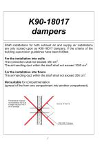
K90-18017 dampers Shaft installations for both exhaust air and supply air installations are only looked upon as K90-18017 dampers, if the criteria of the building supervision guidelines have been fulfilled. For the installation into walls The connection shall not exceed 350 cm2. The air-handling duct within the shaft shall not exceed 1000 cm2. For the installation into floors The air-handling duct within the shaft shall not exceed 350 cm2. Not suitable for compartmentation (spread of fire from one compartment into another compartment). Temperature increase not exceeding 180 K as a single value...
Open the catalog to page 4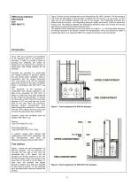
Figure 2 shows the test arrangement for the fireproofing K90-18017 element. The fire-resistant L90 ducts are depending on the diameter mounted into the furnace, e.g. two ducts, in each case one for the smallest diameter and one for the largest. Two fireproofing elements are affixed inside the furnace – one fireproofing element outside the furnace, 2000 mm above the furnace roof. The distance between the fireproofing elements inside and outside the furnace represents the approximate height between floors. The standard time temperature curve is the same as in figure 1, i.e. the fireproofing elements...
Open the catalog to page 5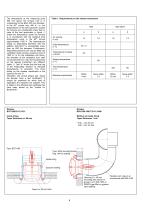
The temperature at the measuring point 500 mm above the furnace roof is in comparison for the BSE, 200 mm diameter, th in the 90 minute only 456 K, i.e. the temperatures of the test specimen outside the furnace are considerably lower than in case of the test specimens in figure 1, where the temperature inside the furnace is in accordance with the standard time th temperature curve in the 90 minute approximately 1000 K. The temperatures acting on fireproofing elements with the addition K90-18017 is considerably lower than on K90 fire dampers. Furthermore, fireproofing elements can only be fitted...
Open the catalog to page 6
Accessories (optional) MS-E - electrical limit switch RT - tee for cleaning SNP-S - male sleeve connection NP - male-male connector NW 100, 125, 160 and 200 (NW 80 only for the insertion into WFR) with a hermetically enclosed release mechanism WBE-K90-18017 Test certificate Z-41.3-619 Resistance class K90-18017 3 W = installation into walls, optionally with a mounting frame type: ER ER-I - steel mounting frame for the embedding with mortar (wet mounting) ER-T WS - steel mounting frame with a fastening plate and dowels, without the embedding with mortar (dry mounting) WP - steel mounting frame...
Open the catalog to page 7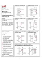
Installation into a service shaft with internal fire load* Installation outside of a service shaft with internal fire load* Lmax. x Damper with a hermetically enclosed release mechanism WBE-K90-18017 Test certificate Z-41.3-619 Installation example inside and outside of shaft walls Please note: For dampers in front of shaft wall (max. 6 m), spirally wound ducting or flexible steel ducts shall be used. Installation into a classified or systemtested shaft Installation outside of a classified or system-tested shaft Lmax. x *Note: Plastic sewer pipes or lines, which are inside the service shaft,...
Open the catalog to page 8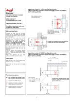
with a hermetically enclosed release mechanism Wet installation with the ER mounting frame WBE-K90-18017 Test certificate Z-41.3-619 Resistance class K90-18017 Installation example inside and outside of shaft walls Wet installation Surrounding gap filled with mortar of group II or III, DIN 1053 or gypsum Insertion into a standard spirally wound ducting (drawing with an exhaust air automaton) ER mounting frame Towards the shaft wall, the mounting frame, type ER, is suitable for the direct connection with WFR, ALUFLEX ductwork or no connection. Towards the room, e.g. cooker hoods (without built-in...
Open the catalog to page 9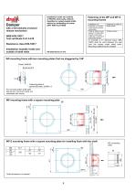
Installation inside and outside of F90/F30 shaft walls, L90/L30 classified or system-tested shafts without an embedding of mortar (DRY INSTALLATION) Fastening of the WP and WP-Z mounting frames Installation into Brickwork or concrete walls without a mortar embedding Walls or shafts of solid gypsum or fireproofing boards, metal stand walls with a covering of fireproofing boards with a hermetically enclosed release mechanism WBE-K90-18017 Test certificate Z-41.3-619 Fastening by means of Metall dowels Wooden screws In principle, a A1 adhesive (type: SBK 2000) shall be used between the wall and...
Open the catalog to page 10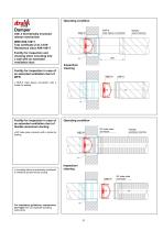
Operating condition with a hermetically enclosed release mechanism SNP-S male sleeve connection Spirally wound ducting WBE-K90-18017 Test certificate Z-41.3-619 Resistance class K90-18017 Facility for inspection and cleaning when mounting into a wall with an extended ventilation duct Inspection/ cleaning Facility for inspection in case of an extended ventilation duct of WFR • SNP-S male sleeve connection with a rubber lip sealing Facility for inspection in case of an extended ventilation duct of flexible aluminium ducting • NP male-male connector with a rubber lip sealing Operating condition...
Open the catalog to page 11
Mounting into floors that have a fire resistance time of 30 - 90 minutes – including a facility for inspection and cleaning Damper with a hermetically enclosed release mechanism WBE-K90-18017 Test certificate Z-41.3-619 Resistance class K90-18017 Installation example: Floors including a facility for inspection and cleaning NP male-male connector by the installer WBE-D 100 mm minimum thickness of the concrete wall For installation guidelines, maintenance and repair see our separate operating instructions Here the inspection cover and connecting collar or inlet spigot can be exchanged. A mounting...
Open the catalog to page 12All Strulik GmbH catalogs and technical brochures
 BEK
BEK15 Pages
 BCF-K90
16 Pages
 BCF-2-K90
19 Pages
 Fire Prevention Part V
22 Pages
 Fire Prevention Part III
82 Pages
 Fire Prevention Part I
213 Pages