- Catalogs
- Strulik GmbH
- Fire Prevention Part I
Fire Prevention Part I

Fire Prevention Part I
This document provides comprehensive technical specifications, installation procedures, and maintenance guidelines for various fire dampers, including models like K90, K30, BKS-2, BK-326, and others. These dampers are designed to prevent the spread of fire through ventilation systems and comply with DIN 4102-6 standards.
- Fire dampers are available in different models and resistance classes (K90/K30), indicating their ability to withstand fire for 90 or 30 minutes.
- Constructed from materials like galvanized steel, stainless steel, and calcium silicate, with options for polyurethane coating.
- Activation mechanisms include fusible links at 72°C, with optional higher temperature links for specific applications.
- Detailed instructions are provided for installing dampers in walls, floors, and light partitions, ensuring proper handling and embedding with mortar.
- Specific dimensions, separation distances, and mounting materials are outlined for secure installation.
- Installation guidelines vary based on wall types, including solid, light partition, and concrete walls.
- The document includes technical data, diagrams, and calculation examples for various damper models.
- Wiring diagrams and mounting instructions for release mechanisms are provided.
- Dampers should be serviced twice a year initially, and annually thereafter if no malfunctions are detected.
- Regular testing of damper functionality is recommended before and after installation.
- Accessories include electrical limit switches, release mechanisms (spring-return motor, direct-current magnet), and pneumatic release options.
- Optional components like smoke detection systems and intumescent dampers are available for enhanced safety.
- All dampers are tested for compliance with DIN 4102-6 standards, with test certificates provided.
- Compliance with European standards, including CENELEC and VDE specifications, is ensured.
- Proper installation and maintenance are crucial for ensuring the effectiveness of fire dampers.
- Regular inspections and use of original spare parts are advised to maintain operational reliability.
This document serves as a comprehensive guide for the selection, installation, and maintenance of fire dampers, ensuring compliance with fire safety standards and optimal performance in various building environments.
Catalog excerpts
Fire Prevention K90 and K30 dampers in accordance with DIN 4102-6 Part I – 09/2006 40 30 Total pressure loss ∆pt [Pa]
Open the catalog to page 1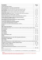
Contents illustrated in photos K90 and K30 dampers in accordance with DIN 4102-6 BK-326-K90/K30 universal fire damper with sheet-metal blade (BKS-2-K90) BKU-N-K90/K30 universal fire damper completely made of calcium silicate BKU-K90/K90 universal fire damper completely made of calcium silicate BKS/BKL/BKV-K90/K90 super damper - is only required under certain circumstances Damper blade projections for BK-326/BKU-N/BKU/BKS/BKL/BKV and BKS-2 Position indicator for supplement floors and release mechanisms for BK-326/BKU/BKS/BKL/BKV and BKS-2 Wiring diagrams and mounting instructions for release mechanisms...
Open the catalog to page 2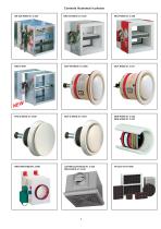
Contents illustrated in photos BK-326-K90/Z-41.3-326
Open the catalog to page 3
Ordering example: BKS-2/EE/B=797xH=503xL=500 Standard damper length; on request, also available in 375 mm Dimensions B x H (width x height) in mm, side H is always the operating side Test certificate Accessories: e.g. electrical limit switch, see page 47 Resistance class K90/K30 in accordance with DIN 4102-6 Summary and ordering example Essential advantages of the universal fire damper After the ventilation system has been put into operation, the damper shall be serviced twice a year. If no malfunctions have been detected after two consecutive examinations, then the dampers only have to be serviced...
Open the catalog to page 4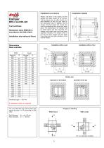
Installation provisions BKS-2 and BK-326 Test certificate Resistance class K90/K30 in accordance with DIN 4102-6 Installation into walls and floors Dimensions Sizes available Please note that in the factory the fire damper has been tested for its function. The fire damper has a safety function and shall therefore be kept dry and clean on the construction site. In addition, the fire damper shall be treated with utmost care until the embedding with mortar has taken place. The functioning of the damper shall be tested before and after mounting. The damper must easily open and close when operated...
Open the catalog to page 5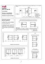
Test certificate Installation into walls and floors Minimum separation for openings within the connected ventilation ducts of non-combustible resistance class. Connection provisions Minimum separations * Distance 60 mm in case of embedding with mortar by hand and 40 mm in case of mechanical pressing process. Components, which in full or in part consist of combustible materials, shall be at a distance of min. 5 cm from the outer face of the fire dampers. This especially applies to externally applied facings and insulating • Please note: Other distances for the usage in combination with electric...
Open the catalog to page 6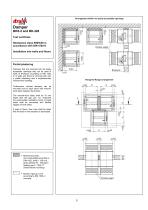
Arrangement within not easily accessible openings BKS-2 and BK-326 Test certificate Resistance class K90/K30 in accordance with DIN 4102-6 Flexible spigot Installation into walls and floors Partial plastering Dampers that are mounted into not easily accessible openings may not be used in walls of brickwork according to DIN 1053 or in walls and floors of concrete with only a partial plastering and a supplementary mineral-wool cladding. Flange-to-flange arrangement Furthermore, several dampers can be mounted next to each other with mineralwool slabs between the frames. The mineral-wool slabs shall...
Open the catalog to page 7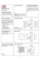
Connection provisions The dampers shall only be connected to such ventilation ducts that due to their design and embedding, as a result of warming up, will not be able to apply considerable forces to the dampers or the walls. BKS-2 and BK-326 Test certificate Resistance class K90/K30 in accordance with DIN 4102-6 Installation into walls and floors Note: In order to interrupt the earth connection of sheet-metal ducts for the installation of flexible spigots, a potential compensator type PO is available. Expansion compensation Flexible spigot, type SS For the following applications a flexible spigot...
Open the catalog to page 8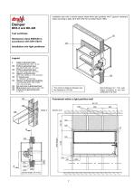
Installation also with a vertical damper blade within light partitions with F gypsum cardboard plates according to table 48 of DIN 4102 Part 4 (edition March 1994) BKS-2 and BK-326 Test certificate Resistance class K90/K30 in accordance with DIN 4102-6 Installation into light partitions The minimum distance between two fire dampers is 120 mm Framework within a light partition wall Angle in galvanized steel, circumferential 25 x 25 x 1,5 mm Profile in galvanized steel, type UW 50 (50 x 40 x 0,5 mm) Profile in galvanized steel, type CW 50 (50 x 48 x 0,5 mm) Gypsum cardboard plate, (GKF, DIN 18180),...
Open the catalog to page 9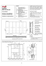
Test certificate Installation into light partitions 2 Angle in galvanized steel, 137 Profile in galvanized steel, galvanized sheet steel, 100-06/125-06 141 Gypsum cardboard plate, material class A, 40 mm thick, 144 Dry wall screw in galvanized steel, Installation also with vertical axis into light partitions. Wall thickness 175 and 200 mm, wall with three layers (RIGIPS system) according to the test certificate no. 831045 of the Technical University Braunschweig. Partition wall of resistance class F90. 1st and 2nd layer: RIGIPS screws for quick 3rd layer: RIGIPS dry wall screws 45 mm. Gaps filled...
Open the catalog to page 10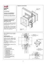
Expansion compensation Flexible spigot, type SS Test certificate Resistance class K90/K30 in accordance with DIN 4102-6 Installation into light partitions Connection provisions for the installation of dampers into light partition walls In principle, fire dampers within light partition walls have a flexible connection, if they are on both sides connected to noncombustible ducts. The flexible spigot of at least standard flammable materials (class B2 according to DIN 4102) and min. 10 cm long (when installed) shall be installed between the damper and the ventilation duct. Flexible spigot, type SS...
Open the catalog to page 11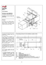
Test certificate Resistance class K90/K30 in accordance with DIN 4102-6 Installation in front of walls with slab lining Expansion compensation Dampers The dampers can be installed outside of walls or floors, if they are connected to tested ventilation ducts having a L90 resistance class. The distance between damper and wall or floor is variable. The dampers shall be fitted with expansion compensators, if ventilation ducts (114) shall be connected. Connecting provisions for the installation outside of walls The dampers shall be suspended in a fireproof manner. The suspension shall comply with...
Open the catalog to page 12All Strulik GmbH catalogs and technical brochures
 BEK
BEK15 Pages
 BCF-K90
16 Pages
 BCF-2-K90
19 Pages
 Fire Prevention Part V
22 Pages
 Fire Prevention Part III
82 Pages
 Fire Prevention Part II
61 Pages