Catalog excerpts

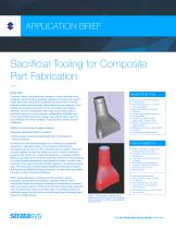
APPLICATION BRIEF Sacrificial Tooling for Composite Part Fabrication Overview Complex, hollow composite parts present a unique manufacturing challenge. Internal tooling, generally referred to as cores, are used to create the hollow features in composite structures when a smooth internal surface finish and seam-free construction are required. Some tooling can be easily removed from the composite part’s design geometry, but any configuration that traps a tool inside requires sacrificial tooling or a more complex, collapsible or inflatable tool. Current sacrificial tooling technology uses eutectic salts, ceramics, cast urethanes or similar materials. These options present several challenges: • No pre-process tooling required to manufacture • Hands-free removal of tool after part consolidation • High temperature and pressure resistance • Limited manual labor required for tool preparation • Capability to create hollow, single-piece, complex parts • Robust construction to survive rough handling • Design-to-part time of days instead of months • Dimensionally stable material • ifficult to handle due to fragile materials D • equires additional tooling to produce R • imits creation of specific geometries due to production or L removal methods One way to avoid these drawbacks is by creating the composite structures in clamshell tooling. This process is performed by manufacturing two halves of the composite part in parallel, which are bonded together to make the hollow structure. If there is sufficient access to the interior of a closed clamshell tool, composite material plies can be added at the interface of the two halves for in-situ bonding. For more complex geometries where access is limited, the part must be cured in two halves and then bonded together in a post-processing step. This secondary process requires additional manufacturing time and sometimes additional tooling, resulting in a seam that may weaken the part or require structural adhesives. FDM® (fused deposition modeling) sacrificial tooling, using a proprietary, dissolvable thermoplastic material called ST-130™, dramatically eases the production process of complicated composite parts with hollow interiors. FDM sacrificial tooling allows the production of a composite part without a bonded seam. It’s created without any additional support tooling and is removed hands-free, shortening lead times from design to part. • Hollow, seamless, complex, onepiece composite structures • Parts with internal surface finish requirements • Lower part volumes for economic suitability • Parts that will not be affected by higher coefficient of thermal expansion (CTE) tooling • Short lead time Composites manufacturing • Cure up to 250 °F (121 °C) with no pressure • Cure pressures up to 90 psi in conjunction with temperatures <210 °F (98 °C) • CTE approximately six times higher than aluminum Figure 1 - FDM sacrificial tooling is easily created from the CAD model of the composite part and prepared for building using Stratasys Insight
Open the catalog to page 1
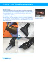
SACRIFICIAL TOOLING FOR COMPOSITE PART FABRICATION Application Outline FDM sacrificial tooling begins with the design of the tool, based on the design of the final composite part. The sacrificial tool is designed to fill the interior of the part and may include trim lines or location features. The sacrificial tool is then processed using Insight™ software (Figure 1), which uses a custom fill pattern that was developed specifically for this material to promote fluid flow during the tool removal process. The sacrificial interior fill pattern also provides adequate strength under autoclave...
Open the catalog to page 2
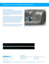
SACRIFICIAL TOOLING FOR COMPOSITE PART FABRICATION Application Demonstration The part shown throughout this application brief is an implementation example of sacrificial tooling. The part is a brake duct inlet used in automotive racing, which provides air from the front bumper to the brakes to keep the calipers and rotors cool from the vast amount of braking heat generated during the race. Figure 4 shows where the duct is located on the vehicle. The duct needed a smooth interior surface finish for unimpeded airflow and was too small to be fabricated using a female mold, which led to the use...
Open the catalog to page 3All STRATASYS GMBH catalogs and technical brochures
-
OBJET30
2 Pages
-
Objet1000 Plus
2 Pages
-
The Stratasys F123 Series
4 Pages
-
Fortus® 380/450mc
21 Pages
-
uPrint® SE/uPrint® SE Plus
12 Pages
-
J750 spec sheet
4 Pages
-
Fortus 900mc spec sheet
2 Pages


