- Catalogs
- Spectrum Antenna & Avionics Systems
- IFF Antenna S07C101-D6
IFF Antenna S07C101-D6

IFF Antenna S07C101-D6
- Frequency Range: 950-1250 MHz
- VSWR: 1.7:1 Max (950-1250 MHz), 1.15:1 Max (1020-1100 MHz)
- Pattern: Nominally Omnidirectional in Azimuth
- Impedance: 50Ω
- Polarization: Vertical (Vertically Mounted)
- RF Power: 1 KW Peak, 15W Mean at 35,000 Feet
- Static Protection: By DC Grounding
- Test Probe: 18 dB (±0.75dB) Isolation at 1090 MHz, BNC Female Standard
- Temperature Range: -54°C to +90°C
- Altitude: 50,000 Feet
- Weight: 90 Grams (Max)
- Height: 76 mm (Max)
- Colour: Black
- Finish: Mat
- Connector: Aerial Feed - TNC Female Standard
- Installation: Four fixing holes with 5.5 mm diameter, counter-bored 12.7 mm. Use factory-supplied drawings and instructions for installation.
Catalog excerpts
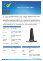
S07C101-D6 is a light weight low profile IFF antenna, designed for operating in the frequency band of 950-1250 MHZ. This antenna is compatible with military aircraft IFF systems. Electrical design involves filters and matching circuits coupled to a broadband monopole terminated with a co-axial connector providing virtually perfect omni-directivity over the full operating range. The antenna is provided with a electrically coupled test probe for online system testing. Shell is vacuum moulded from single-piece glass to provide a rugged and reliable aerodynamic structure for withstanding the extreme environmental conditions experienced on military aircrafts. S07C101-D6 is designed to meet military, regulatory and statutory standards. Frequency Range VSWR Test Probe Pattern Impedance Polarization RF Power Static Protection 950-1250 MHz 1.7:1 Max (950-1250 MHZ) 1.15:1 Max (1020-1100 MHZ) 18 dB (± 0.75dB) Isolation at 1090 MHz Nominally Omnidirectional in Azimuth 500 Vertical (Vertically Mounted) 1 KW Peak, 15W Mean at 35000 Feet By DC Grounding MECHANICAL SPECIFICATION Weight Height Colour Finish Connector Dimension Temperature Range : -54°C to +90°C Altitude : 50,000 Feet Generally in accordance with MIL-STD-810 90 Grams (Max) 76 mm (Max) Black Mat Aerial Feed - TNC Female Standard Test Probe - BNC Female Standard Refer Drawing Overleaf Contactforcustom requirements
Open the catalog to page 1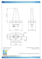
DRAWING SPECIFICATION FOR IFF ANTENNA S07C101-D6 Four fixing hole with 5.5 mm diameter Counter-bored 12.7 mm For installation use factory supplied drawings and instructions Spectrum Antenna & Avionics Systems (P) Ltd, Cochin, India. Contact for custom requirements
Open the catalog to page 2All Spectrum Antenna & Avionics Systems catalogs and technical brochures
 Telemetry Antenna S04D101-D4
2 Pages
 IFF Antenna S07C202-D6
2 Pages
 TACAN Antenna S07C102-D6
2 Pages
 UHF Antenna S12C102-C0
2 Pages