C2
C2
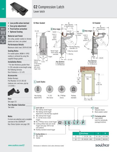
- Material: Zinc alloy, powder coated or chrome plated, and steel, zinc plated.
- Maximum static load: 200 N (45 lbf).
- Sealing: NEMA 4 / IP65 enabled with supplied gasket.
- Door Thickness: Minimum 1 mm (0.04 inches) to Maximum 5 mm (0.20 inches).
- Non-locking and key-locking options available.
- Key-locking styles keyed CH751 with two flat keys supplied.
- Various recess options including Hex, Phillips, and Railway standard.
- Textured chrome and black powder coated finishes available.
- Multiple grip ranges available, adjustable for different applications.
- For door thickness greater than 5 mm, calculate screw length using: Door thickness + 12 mm (0.47 inches).
- Includes serrated mounting screws and optional rubber bumper to adjust grip range.
- Low profile when latched, easy grip adjustment, and push button actuation.
- Optional sealing for enhanced protection.
- Integrated bumper screw for added stability.
Catalog excerpts
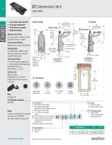
Lever latch Low profile when latched Easy grip adjustment Push button actuation Optional Sealing Zinc alloy, powder coated or chrome plated and steel, zinc plated Maximum static load: 200 N (45 lbf) Installation Notes * For door thickness greater than 5 (.20) calculate screw length using the following formula: Door thickness + 12 (.47) M5 adjusting screws Lever in raised (open) position *Serrated Mounting Screw M5 x 16 Sealing Notes For sealed option, NEMA 4 / IP65 sealing is achieved by using the supplied flange gasket. B when adjusted to maximum grip Lever in raised (open) position Performance Details B when adjusted to maximum grip A Raised trigger (flush version available) Optional keylock or tool access (available with raised trigger only) Mounting bracket Housing Door Thickness 1 (.04) Minimum 8 (.32) Maximum Door Thickness 1 (.04) Minimum 5 (.20) Maximum Frame Door ACTUAL SIZE Accessories Rubber Bumper: Part Number: C2-25-301-82 (reduces min. and max. grip by 1.6 (0.06) ) Part Number Selection ________________________________________________________________________________ See table Notes For lock core selection and a complete overview of the SOUTHCO® Key-Choice System see page 190 L Lock style 1 Non-locking raised trigger 2 Key-locking raised trigger keyed CH751 (two flat keys supplied) 3 Non-locking flush trigger 4 4 (.16) Hex recess raised trigger 10 No. 2 Phillips recess raised trigger 13 Locking without lock core raised trigger (see page 190 for lock core options) 14 Railway standard raised trigger F Finish 1 Textured chrome 5 Black powder coated S Sealing Option 3 Non-sealed 4 Sealed Dimensions in millimeters (inch) unless otherwise stated P Packaging option 3 Layer packed (omit for individually packaged latches)
Open the catalog to page 1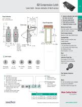
Lever latch · Access indicator of latch access Visual Indicator • F eature indicates that latch has been accessed • Easy grip adjustment • Push button actuation • Integrated bumper screw B when adjusted to maximum grip Green – Unaccessed Red – Accessed (Operated) Panel Preparation Material and Finish Zinc alloy, powder coated or chrome plated and steel, zinc plated NEMA 4 and IP65 enabled using supplied gasket. Optional key lock or 1 (.04) Min. tool access 8(.32) Max. (available with raised trigger only) ACTUAL SIZE Installation Notes * For door thickness greater than 5 (.20) calculate screw...
Open the catalog to page 2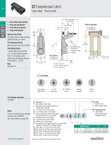
Lever latch · Push to lock B when adjusted to maximum grip Low profile when latched Easy grip adjustment Push button actuation Integrated bumper Panel Preparation Grip range Frame Door 2x R 3 (.12) Maximum Zinc alloy, powder coated or chrome plated and steel, zinc plated Performance Details Maximum static load: 200 N (45 lbf) *Serrated Mounting Screw M5 x 16 Mounting bracket Housing Installation Notes * Serrated Mounting Screw M5 x 16. For door thickness greater than 5 (.20) calculate screw length using the following formula: Door thickness + 12 (.47) Door Thickness 1 (.04) Minimum 5 (.20) Maximum...
Open the catalog to page 3