- Catalogs
- Solitron Devices
- SD11710
SD11710

SD11710
- Drain-Source Voltage (VDS): 700V
- Continuous Drain Current (ID): 140A at 25°C, 99A at 100°C
- On-Resistance (RDS(on)): 15mΩ
- Gate-Source Voltage (VGS): 23V to -10V
- Maximum Power Dissipation (PD): 455W
- Junction-to-Case Thermal Resistance (RθJC): 0.22 to 0.33 °C/W
- Operating Junction Temperature (TJ): -55°C to +175°C
- Storage Temperature (TSTG): -55°C to +150°C
- Soldering Temperature: 300°C for 10 seconds
- Isolated backside and hermetically sealed TO-258 package
- Low capacitances and gate charge for fast switching
- Stable operation at high junction temperatures
- Superior avalanche ruggedness and RoHS compliance
- Static: Drain-Source Breakdown Voltage of 700V, Gate Threshold Voltage of 1.9 to 2.4V
- Dynamic: Input Capacitance of 4500pF, Total Gate Charge of 215nC
- Diode Forward Voltage of 3.4V at 40A
- Reverse Recovery Time of 40ns
Catalog excerpts
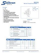
700V SiC N-Channel Power MOSFET - 1 ISOLATED BACKSIDE TO-258 HERMETICALLY SEALED PACKAGE MIL-PRF-19500 SCREENING AVAILABLE LOW CAPACITANCES AND LOW GATE CHARGE FAST SWITCHING SPEED DUE TO LOW INTERNAL GATE RESISTANCE (ESR) STABLE OPERATION AT HIGH JUNCTION TEMPERATURE, TJ(MAX) = 175 °C ORDERING GUIDE FAST AND RELIABLE BODY DIODE SUPERIOR AVALANCHE RUGGEDNESS ROHS COMPLIANT ABSOLUTE MAXIMIMUM RATINGS (TC = 25°C) SYMBOL Drain-Source Voltage Gate-Source Voltage (dynamic) Continuous Drain Current 700V SiC N-Channel Power MOSFET Pulsed Drain Current * Maximum Power Dissipation Linear Derating Factor * Repetitive rating: pulse width and case temperature limited by maximum junction temperature. THERMAL AND MECHANICAL CHARACTERISTICS SYMBOL RØJC Junction-to-Case Thermal Resistance Operating Junction Temperature Storage Temperature Soldering Temperature for 10s (1.6mm from case) Mounting Torque, 6-32 or M3 Screw Wt Package Weight EMAIL: sales@solitrond
Open the catalog to page 1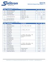
700V SiC N-Channel Power MOSFET - 2 ELECTRICAL CHARACTERISTICS, STATIC (TJ = 25°C) SYMBOL TEST CONDITIONS Drain-Source Breakdown Voltage Gate Threshold Voltage Threshold Voltage Coefficient ∆VGS(th)/∆TJ IDSS Zero Gate Voltage Drain Current Gate-Source Leakage Current * Pulse test: pulse width < 380 µs, duty cycle < 2%. ELECTRICAL CHARACTERISTICS, DYNAMIC (TJ = 25°C) SYMBOL TEST CONDITIONS Input Capacitance Reverse Transfer Capacitance Output Capacitance Total Gate Charge Gate-Source Charge Gate-Drain Charge Turn-On Delay Time Voltage Fall Time Turn-Off Delay Time Voltage Rise Time Turn-On Switching...
Open the catalog to page 2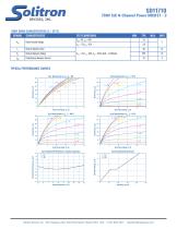
700V SiC N-Channel Power MOSFET - 3 BODY DIODE CHARACTERISTICS (TJ = 25°C) SYMBOL Diode Forward Voltage Reverse Recovery Time Reverse Recovery Charge Peak Reverse Recovery Current TEST CONDITIONS TYPICAL PERFORMANCE CURVES Fig 1: Drain Current vs. VDS , VGS = 20V Fig 6: Gate Charge Characteristics Fig 5: Normalized On-Resistance vs. Junction Temperature Normalized On-Resistance, RDS(on) (mΩ) Solitron Devices, Inc. • 901 Sansburys Way, West Palm Beach, Florida 33411, USA • +1 561-848-4311 • sales@s
Open the catalog to page 3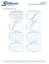
700V SiC N-Channel Power MOSFET - 4 TYPICAL PERFORMANCE CURVES, CONT. Fig 7: Capacitance vs. Drain-Source Voltage Fig 8: Pulsed Drain Current vs. Gate Source Voltage Pulsed Drain Current, IDS (A) Fig 12: Switching Energy Off vs. Drain Source Voltage Rg = 4Ω Fig 13: Switching Energy vs. Gate Resistance ID = 50A Fig 14: Switching Energy vs. Junction Temperature ID = 50A, Rg = 4Ω Fig 11: Switching Energy On vs. Drain Source Voltage Rg = 4Ω Solitron Devices, Inc. • 901 Sansburys Way, West Palm Beach, Florida 33411, USA • +1 561-848-4311 • sale
Open the catalog to page 4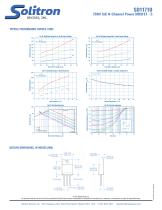
700V SiC N-Channel Power MOSFET - 5 TYPICAL PERFORMANCE CURVES, CONT. Fig 15: Switching Energy On vs. Drain Source Voltage Fig 17: Switching Energy vs. Gate Resistance Fig 18: Threshold Voltage vs. Junction Temperature VGS = VDS, ID = 4mA Threshold Voltage, VGS(th) (V) Fig 16: Switching Energy Off vs. Drain Source Voltage Not characterized for linear user RDS(on) Limit Fig 19: Safe Operating Area Junction to Case Temperature, Zthjc (°C/W) Single Pulse OUTLINE DIMENSIONS, IN INCHES (MM) 0.694 [17.63] 0.684 [17.37] © 2023 Solitron Devices, Inc. This document is believed to be correct at the time...
Open the catalog to page 5All Solitron Devices catalogs and technical brochures
 SD11461
3 Pages
 SMF404
3 Pages
 SD11721
6 Pages
 SD11714
3 Pages
 SD11705
5 Pages
 2N5114 | 2N5115 | 2N5116
2 Pages
 2N5911 | 2N5912
2 Pages
 2N4416 | 2N4416A
2 Pages
 2N4391 | 2N4392 | 2N4393
2 Pages
 2N4338 | 2N4339
3 Pages
 2N4901 | 2N4902 | 2N4903
2 Pages
 2N3957 | 2N3958
2 Pages
 2N3821 | 2N3822
2 Pages
 SD11487
3 Pages
 SD11812
2 Pages
 SD11800
3 Pages
 SD11801
3 Pages
 SD11809
2 Pages
 SD11804
3 Pages
 SD11803
3 Pages

