- Catalogs
- SICK SENSOR INTELLIGENCE
- WT100-2 energetic
WT100-2 energetic

WT100-2 energetic
The document provides detailed specifications for the WT100-2 sensor system, highlighting its capabilities and operational parameters:
- Sensing range: 0 to 750 mm, with a maximum of 1,200 mm.
- Light spot diameter/distance: 75 mm at 1 m.
- Supply voltage: DC 10 to 30 V.
- Output current: Maximum 100 mA.
- Max. switching frequency: 1,000 Hz.
- Max. response time: ≤ 0.5 ms.
- Enclosure rating: IP 65.
- Protection class: III.
- Circuit protection includes reverse polarity and short-circuit protection.
- Ambient operating temperature: -25 to +55°C.
Key safety notes include:
- Read operating instructions before use.
- Only trained specialists should perform connection, mounting, and setting.
- The sensor is not a safety component under the EU Machinery Directive.
- Protect the device from moisture and contamination during commissioning.
The WT100-2 is designed for optical, non-contact detection of objects, animals, and persons. Any other use or modification voids the warranty.
Steps for proper installation and setup include:
- Verify application conditions by comparing the switching distance and remission capability with the provided diagram.
- Mount the sensor using a suitable bracket, ensuring the maximum permissible tightening torque is < 0.5 Nm.
- Connect sensors in a voltage-free state, following connection type instructions.
- Align the sensor with the object, ensuring the red light beam hits the center and the optical opening is clear.
- Adjust sensitivity using the potentiometer and verify operation using provided diagrams.
Common issues and solutions include:
- Green LED does not light up: Check power supply and connections. If power is stable, the sensor may be faulty and require replacement.
- Yellow LED issues: Adjust sensitivity or use sensors with background suppression if the remission capability of the background or object is excessive or insufficient.
SICK sensors require minimal maintenance. Recommendations include:
- Regularly clean optical surfaces.
- Check the integrity of threaded and plug connections.
Sensors should be disposed of according to national regulations, with an emphasis on recycling materials, especially precious metals.
Catalog excerpts

OPERATING INSTRUCTION Miniature photoelectric sensor
Open the catalog to page 1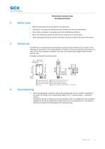
Sensor Intelligence. Photoelectric proximity sensor Operating instructions Read the operating instructions before commissioning. Connection, mounting, and setting may only be performed by trained specialists. Not a safety component in accordance with the EU Machinery Directive. When commissioning, protect the device from moisture and contamination. These operating instructions contain information required during the life cycle of the sensor. The WT100-2 is an opto-electronic photoelectric proximity sensor (referred to as "sensor" in the following) for the optical, non-contact detection of objects,...
Open the catalog to page 2
Commissioning Function reserve Distance in m (feet) Image 1: H Mount the sensor using a suitable mounting bracket (see the SICK range of accessories). Note the sensor's maximum permissible tightening torque of < 0.5 Nm. The sensors must be connected in a voltage-free state (VS = 0 V). The information in the graphics [B] must be observed, depending on the type of connection: – Male connector connection: pin assignment – Cable: core color Only apply voltage/switch on the power supply (VS > 0 V) once all electrical connections have been completed. The green LED indicator lights up on the sensor....
Open the catalog to page 3
Sensor with potentiometer: The sensitivity (sensing range) is adjusted with the potentiometer (type: 270°). Clockwise rotation: sensitivity (sensing range) increased; counterclockwise rotation: sensitivity (sensing range) reduced. We recommend placing the switching state in the object, e.g., see Graphic F. Once the sensitivity has been adjusted, the object is removed from the path of the beam. The switching output changes (see Graphic C). The sensor is adjusted and ready for operation. Refer to Graphics C and G to check the func‐ tion. If the switching output fails to behave in accordance with...
Open the catalog to page 4
Fault diagnosis Table indicates which measures are to be taken if the sensor stops working. Tab_Fault diagnosis LED indicator/fault pattern / Green LED does not light up or flickers / Sensor is still ready for operation, but the operating conditions are not ideal (operating reserve factor between 0.9 and 1.1) / Green LED does not light up or flickers Green LED does not light up / Green LED does not light up Check the operating conditions: Fully align the beam of light (light spot) with the object. / Clean the optical surfaces / Readjust the Sensor is still ready for operation, sensitivity (potentiometer)...
Open the catalog to page 5
Yellow LED lights up, no object in the path of the beam / Remission capability of the back‐ ground is excessive / Yellow LED lights up, no object in the path of the beam Remission capability of the back‐ ground is excessive Check changes to the back‐ ground. Reduce the sensitivity of the sensor or use sensors with background suppression / Check changes to the back‐ ground. Reduce the sensitivity of the sensor or use sensors with background suppression Yellow LED does not light up (applies to light switching devices) or yellow LED lights up (applies to dark switching devices), object is in the...
Open the catalog to page 6
Sensor Intelligence. Vor der Inbetriebnahme die Betriebsanleitung lesen. Anschluss, Montage und Einstellung nur durch Fachpersonal. Kein Sicherheitsbauteil gemaS EU-Maschinenrichtlinie. Gerat bei Inbetriebnahme vor Feuchte und Verunreinigung schutzen. Diese Betriebsanleitung enthalt Informationen, die wahrend des Lebenszyklus des Sensors Die WT100-2 ist ein optoelektronischer Reflexions-Lichttaster (im Folgenden Sensor genannt) und wird zum optischen, beruhrungslosen Erfassen von Sachen, Tieren und Personen eingesetzt. Bei jeder anderen Verwendung und bei Veranderungen am Produkt verfallt jeglicher...
Open the catalog to page 7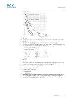
Inbetriebnahme Function reserve Den Sensor an einen geeigneten Befestigungswinkel montieren (siehe SICK-Zubehör-Pro‐ gramm). Maximal zulässiges Anzugsdrehmoment des Sensors von < 0.5 Nm beachten. Anschluss der Sensoren muss spannungsfrei (VS = 0 V) erfolgen. Je nach Anschlussart sind die Informationen in den Grafiken [vgl. B] zu beachten: – Steckeranschluss: Pinbelegung – Leitung: Adernfarbe Erst nach Anschluss aller elektrischen Verbindungen die Spannungsversorgung (VS > 0 V) anlegen bzw. einschalten. Am Sensor leuchtet die grüne Anzeige-LED. Erläuterungen zum Anschlussschema (Grafik B): Schaltausgang...
Open the catalog to page 8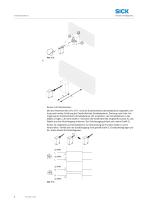
Sensor mit Potentiometer: Mit dem Potentiometer (Art: 270°) wird die Empfindlichkeit (Schaltabstand) eingestellt. Dre‐ hung nach rechts: Erhöhung der Empfindlichkeit (Schaltabstand), Drehung nach links: Ver‐ ringerung der Empfindlichkeit (Schaltabstand). Wir empfehlen, den Schaltabstand in das Objekt zu legen, z.B. siehe Grafik F. Nachdem die Empfindlichkeit eingestellt worden ist, das Objekt aus dem Strahlengang entfernen. Der Schaltausgang ändert sich (siehe Grafik C). Sensor ist eingestellt und betriebsbereit. Zur Überprüfung der Funktion Grafik C und G heranziehen. Verhält sich der Schaltausgang...
Open the catalog to page 9
Fehlerdiagnose Tabelle I zeigt, welche Maßnahmen durchzuführen sind, wenn die Funktion des Sensors nicht mehr gegeben ist. Tab_Fehlerdiagnose Anzeige-LED / Fehlerbild / Grüne LED leuchtet nicht bzw. fla‐ ckert / Sensor ist noch betriebsbereit, aber die Betriebsbedingungen sind nicht optimal (Funktionsre‐ servefaktor zwischen 0,9 und 1,1) / Green LED does not light up or flickers grüne LED leuchtet nicht / Green LED does not light up Betriebsbedingungen prüfen: Lichtstrahl (Lichtfleck) vollständig auf das Objekt ausrichten / Reini‐ gung der optischen Flächen / Empfindlichkeit (Potentiometer) Sensor...
Open the catalog to page 10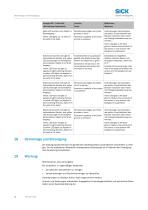
Anzeige-LED / Fehlerbild / gelbe LED leuchtet, kein Objekt im Strahlengang / Remissionsvermögen des Hinter‐ grundes zu hoch / Yellow LED lights up, no object in the path of the beam Remission capability of the back‐ ground is excessive Veränderungen des Hintergrun‐ des prüfen. Empfindlichkeit des Sensors reduzieren oder Taster mit Hintergrundausblendung ver‐ wenden / Check changes to the back‐ ground. Reduce the sensitivity of the sensor or use sensors with background suppression Gelbe LED leuchtet nicht (gilt für hellschaltende Geräte), bzw. gelbe LED leuchtet (gilt für dunkelschal‐ tende Geräte),...
Open the catalog to page 11All SICK SENSOR INTELLIGENCE catalogs and technical brochures
 REGISTRATION SENSORS
24 Pages
 CLV63x, CLV64x, CLV65x
102 Pages
 WTB16 Bluetooth®
135 Pages
 WE9LC-3_A71
3 Pages
 Safety Switches
20 Pages
 Automation light grids
8 Pages
 Encoders and Inclination Sensors
32 Pages
 Proximity Sensors
324 Pages
 Dust measuring devices
172 Pages
 Detection and Ranging Solutions
124 Pages
 Distance Sensors
404 Pages
 Vision
124 Pages
 Top-Products from SICK
556 Pages
 Fluid Sensors
243 Pages
 Registration Sensors
276 Pages
 Magnetic Cylinder Sensors
164 Pages
 Hand-Held Scanners IDMx
48 Pages
 IDENTIFICATION SOLUTIONS
24 Pages
 Our identification solutions
8 Pages
 FLOWSIC300 Ultrasonic Gas Flow Meter
177 Pages
 FLOWSIC300 Gas flow meters
12 Pages
 FLOWSIC500 Gas flow meters
16 Pages
 FLOWSIC600 Ultrasonic Gas Flow Meter
138 Pages
 FLOWSIC600 Gas Flow Meter
16 Pages
 ConVer
12 Pages
 GM32 In-situ gas analyzers
28 Pages
 GM35 In-Situ IR Gas Analyzer
16 Pages
 Encoders
788 Pages
 Photoelectric Sensors
949 Pages
 Opto Electronic Protective Devices
712 Pages
 GMS800 Extractive Gas Analyzers
20 Pages
 VPS Pro Profiling systems
20 Pages
 G6 - Global Sensor
20 Pages


- Airport camera
- Surveillance radar
- Laser scanner
- Aeronautic laser scanner
- Non-contact laser scanner
- Spark optical emission camera
- Land-based radar
- Airport barcode reader
- Measurement laser scanner
- 2D barcode reader
- Fixed barcode reader
- 1D barcode reader
- Baggage barcode reader
- 3D laser scanner
- RFID airport reader
- Portable barcode reader
- Portable RFID reader
- Detection radar
- USB barcode reader
- Boarding pass barcode reader