- Catalogs
- SICK SENSOR INTELLIGENCE
- WT100-2 with background suppression
WT100-2 with background suppression

WT100-2 with background suppression
- Read operating instructions before use.
- Only trained specialists should handle installation and adjustments.
- The device is not a safety component under the EU Machinery Directive.
- Protect from moisture and contamination during commissioning.
The WT100-2 is an opto-electronic photoelectric proximity sensor for non-contact detection of objects, animals, and persons. Any other use voids the warranty.
- Check application conditions and adjust sensing range using the provided diagram.
- Mount the sensor with a suitable bracket, not exceeding the maximum torque.
- Connect sensors in a voltage-free state; apply voltage after connections are complete.
- Align the sensor with the object and adjust the sensing range using the potentiometer.
Refer to the fault diagnosis table for troubleshooting. Common issues include:
- Green LED not lighting up due to power issues.
- Yellow LED indicating incorrect settings.
Dispose of the sensor according to country-specific regulations, focusing on recycling materials.
SICK sensors are maintenance-free but recommend regular cleaning of lens surfaces and checking connections. No modifications should be made.
The sensor operates with a direct reflection detection system with background suppression. Reflectivity values are 6% for black, 18% for gray, and 90% for white, based on DIN 5033 standards.
- Verify operating conditions and adjust the sensing range as per diagrams.
- Mount the sensor using appropriate brackets, ensuring a maximum torque of 0.5 Nm.
- Connect the sensor while powered off, following pin-out instructions.
- Align the sensor so the red light beam hits the object center.
After setup, the sensor is ready for use. Use diagrams to verify functionality. Refer to diagnostics if issues arise.
Troubleshooting measures for LED indicator patterns include:
- Green LED flickering: Check alignment and clean optics.
- No green LED: Check power supply and connections.
- Yellow LED issues: Adjust sensing range or sensitivity.
Dispose of the sensor according to national regulations, focusing on recycling valuable materials.
Key parameters include a sensing range of 10 to 100 mm, with a maximum range of 4 to 140 mm. The supply voltage is DC 10 to 30 V, and the output current is 100 mA. The maximum switching frequency is 1,000 Hz, and the maximum response time is ≤ 0.5 ms. The enclosure rating is IP 67, and the protection class is III.
For optimal performance, increase the sensing range and maintain appropriate distance. Regular maintenance includes cleaning optical surfaces and checking connections.
Compliance with national disposal regulations is emphasized, advocating for recycling materials. Periodic checks are advised despite no regular maintenance requirement.
Environmental operating temperatures range from -25 to +55°C. Conditions for operation include a light/dark ratio of 1:1 and signal transit time with resistive load.
Catalog excerpts

OPERATING INSTRUCTION WT100-2 with background suppression Miniature photoelectric sensor
Open the catalog to page 1
Sensor Intelligence. Photoelectric proximity sensor Operating instructions Read the operating instructions before commissioning. Connection, mounting, and setting may only be performed by trained specialists. Not a safety component in accordance with the EU Machinery Directive. When commissioning, protect the device from moisture and contamination. These operating instructions contain information required during the life cycle of the sensor. The WT100-2 is an opto-electronic photoelectric proximity sensor (referred to as "sensor" in the following) for the optical, non-contact detection of objects,...
Open the catalog to page 2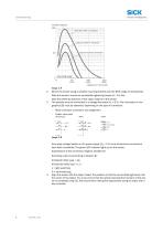
Commissioning Function reserve 100 white 90 %/90 % remission Operating range Distance in mm (inch) Image 1: H Mount the sensor using a suitable mounting bracket (see the SICK range of accessories). Note the sensor's maximum permissible tightening torque of < 0.5 Nm. Note the preferred direction of the object relative to the sensor. The sensors must be connected in a voltage-free state (VS = 0 V). The information in the graphics [B] must be observed, depending on the type of connection: – Male connector connection: pin assignment – Cable: core color Only apply voltage/switch on the power supply...
Open the catalog to page 3
Sensor with potentiometer: The sensing range is adjusted with the potentiometer (type: 270°). Clockwise rotation: sen‐ sing range increased; counterclockwise rotation: sensing range reduced. We recommend placing the switching state in the object, e.g., see Graphic F. Once the sensing range has been adjusted, the object is removed from the path of the beam, which causes the back‐ ground to be suppressed and the switching output to change (see Graphic C). The sensor is adjusted and ready for operation. Refer to Graphics C and G to check the func‐ tion. If the switching output fails to behave in...
Open the catalog to page 4
Fault diagnosis Table indicates which measures are to be taken if the sensor stops working. Tab_Fault diagnosis LED indicator/fault pattern / Green LED does not light up or flickers / Sensor is still ready for operation, but the operating conditions are not ideal (operating reserve factor between 0.9 and 1.1) / Green LED does not light up or flickers Green LED does not light up / Green LED does not light up Check the operating conditions: Fully align the beam of light (light spot) with the object. / Clean the optical surfaces / Readjust the Sensor is still ready for operation, sensitivity (potentiometer)...
Open the catalog to page 5
Yellow LED does not light up (applies to light switching devices) or yellow LED lights up (applies to dark switching devices), object is in the path of the beam / / Distance between the sensor and the background is too short / Reduce the sensing range, see Graphic F / / Distance between the sensor and the background is too short Reduce the sensing range, see Graphic F Yellow LED does not light up (applies to light switching devices) or yellow LED lights up (applies to dark switching devices), object is in the path of the beam Yellow LED does not light up (applies to light switching devices) or...
Open the catalog to page 6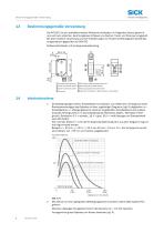
BestimmungsgemaBe Verwendung Sensor Intelligence. Die WT100-2 ist ein optoelektronischer Reflexions-Lichttaster (im Folgenden Sensor genannt) und wird zum optischen, beruhrungslosen Erfassen von Sachen, Tieren und Personen eingesetzt. Bei jeder anderen Verwendung und bei Veranderungen am Produkt verfallt jeglicher Gewahrleis- tungsanspruch gegenuber der SICK AG. 2 Den Sensor an einen geeigneten Befestigungswinkel montieren (siehe SICK-Zubehor-Pro- Maximal zulassiges Anzugsdrehmoment des Sensors von < 0.5 Nm beachten. Vorzugsrichtung des Objektes zum Sensor beachten [vgl. A].
Open the catalog to page 7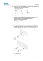
Anschluss der Sensoren muss spannungsfrei (VS = 0 V) erfolgen. Je nach Anschlussart sind die Informationen in den Grafiken [vgl. B] zu beachten: – Steckeranschluss: Pinbelegung – Leitung: Adernfarbe Erst nach Anschluss aller elektrischen Verbindungen die Spannungsversorgung (VS > 0 V) anlegen bzw. einschalten. Am Sensor leuchtet die grüne Anzeige-LED. Erläuterungen zum Anschlussschema (Grafik B): Schaltausgang Q (gemäß Grafik B): WT100-2P (PNP: Last -> M) WT100-2N (NPN: Last -> L+) L = hellschaltend 4 D = dunkelschaltend Sensor auf Objekt ausrichten. Positionierung so wählen, dass der rote Sendelichtstrahl...
Open the catalog to page 8
Mit dem Potentiometer (Art: 270°) wird der Schaltabstand eingestellt. Drehung nach rechts: Erhöhung des Schaltabstandes, Drehung nach links: Verringerung des Schaltabstandes. Wir empfehlen, den Schaltabstand in das Objekt zu legen, z.B. siehe Grafik F. Nachdem der Schaltabstand eingestellt worden ist, das Objekt aus dem Strahlengang entfernen, der Hin‐ tergrund wird dabei ausgeblendet und der Schaltausgang ändert sich (siehe Grafik C). Sensor ist eingestellt und betriebsbereit. Zur Überprüfung der Funktion Grafik C und G heranziehen. Verhält sich der Schaltausgang nicht gemäß Grafik C, Einsatzbedingungen...
Open the catalog to page 9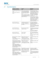
Tab_Fehlerdiagnose Anzeige-LED / Fehlerbild / Grüne LED leuchtet nicht bzw. fla‐ ckert / Sensor ist noch betriebsbereit, aber die Betriebsbedingungen sind nicht optimal (Funktionsre‐ servefaktor zwischen 0,9 und 1,1) / Green LED does not light up or flickers grüne LED leuchtet nicht / Green LED does not light up Betriebsbedingungen prüfen: Lichtstrahl (Lichtfleck) vollständig auf das Objekt ausrichten / Reini‐ gung der optischen Flächen / Empfindlichkeit (Potentiometer) Sensor is still ready for operation, neu einstellen / Schaltabstand überprüfen und ggf. anpassen, but the operating conditions...
Open the catalog to page 10
Sensor Intelligence. Die Entsorgung des Sensors hat gemaS den landerspezifisch anwendbaren Vorschriften zu erfol- gen. Fur die enthaltenen Wertstoffe (insbesondere Edelmetalle) ist im Rahmen der Entsorgung eine Verwertung anzustreben. SICK-Sensoren sind wartungsfrei. Wir empfehlen, in regelmaSigen Abstanden die optischen Grenzflachen zu reinigen Verschraubungen und Steckverbindungen zu uberprufen Veranderungen an Geraten durfen nicht vorgenommen werden. Irrtumer und Anderungen vorbehalten. Angegebene Produkteigenschaften und technische Daten stellen keine Garantieerklarung dar. Detecteur a reflexion...
Open the catalog to page 11All SICK SENSOR INTELLIGENCE catalogs and technical brochures
 REGISTRATION SENSORS
24 Pages
 CLV63x, CLV64x, CLV65x
102 Pages
 WTB16 Bluetooth®
135 Pages
 WE9LC-3_A71
3 Pages
 Safety Switches
20 Pages
 Automation light grids
8 Pages
 Encoders and Inclination Sensors
32 Pages
 Proximity Sensors
324 Pages
 Dust measuring devices
172 Pages
 Detection and Ranging Solutions
124 Pages
 Distance Sensors
404 Pages
 Vision
124 Pages
 Top-Products from SICK
556 Pages
 Fluid Sensors
243 Pages
 Registration Sensors
276 Pages
 Magnetic Cylinder Sensors
164 Pages
 Hand-Held Scanners IDMx
48 Pages
 IDENTIFICATION SOLUTIONS
24 Pages
 Our identification solutions
8 Pages
 FLOWSIC300 Ultrasonic Gas Flow Meter
177 Pages
 FLOWSIC300 Gas flow meters
12 Pages
 FLOWSIC500 Gas flow meters
16 Pages
 FLOWSIC600 Ultrasonic Gas Flow Meter
138 Pages
 FLOWSIC600 Gas Flow Meter
16 Pages
 ConVer
12 Pages
 GM32 In-situ gas analyzers
28 Pages
 GM35 In-Situ IR Gas Analyzer
16 Pages
 Encoders
788 Pages
 Photoelectric Sensors
949 Pages
 Opto Electronic Protective Devices
712 Pages
 GMS800 Extractive Gas Analyzers
20 Pages
 WT100-2 energetic
47 Pages
 VPS Pro Profiling systems
20 Pages
 G6 - Global Sensor
20 Pages


- Airport camera
- Surveillance radar
- Laser scanner
- Aeronautic laser scanner
- Non-contact laser scanner
- Spark optical emission camera
- Land-based radar
- Airport barcode reader
- Measurement laser scanner
- 2D barcode reader
- Fixed barcode reader
- 1D barcode reader
- Baggage barcode reader
- 3D laser scanner
- RFID airport reader
- Portable barcode reader
- Portable RFID reader
- Detection radar
- USB barcode reader
- Boarding pass barcode reader