- Catalogs
- SECO TOOLS
- Taper-Face Toolholders.pdf
Taper-Face Toolholders.pdf

Taper-Face Toolholders.pdf
- The document discusses the importance of the machine tool interface in machining processes, emphasizing the need for optimized performance and reliability. It highlights two critical interfaces: machine-toolholder and toolholder-cutting tool.
- For optimal machining results, the machine-toolholder interface must be maximally rigid. This can be achieved by reducing toolholder length and increasing bearing surface, such as using Taper-Face contact.
- Key requirements include rigidity, clamping technology, tightening force, transmittable torque, stability, balancing quality, repeat accuracy, run-out precision, vibration absorption, ease of use, lifetime, and cost.
- Seco Tools offers a range of Taper-Face tooling systems, including BT TF, CAT TF, and DIN TF, catering to different markets globally.
- The Taper-Face Spindle System uses elastic deformation to achieve simultaneous fit of both taper and flange face, enhancing rigidity and precision.
- Taper-Face contact provides significantly higher rigidity and eliminates axial movement at high speeds, improving machining accuracy and repeatability.
- The product range includes various holders such as Steadyline™, Shell mill holders, Shrinkfit holders, and more, suitable for different spindle sizes and applications.
- The document provides feedback from the Asia Pacific and NAFTA markets, listing machine tool builders that utilize Taper-Face spindle systems.
- Taper-Face holders can be fitted into conventional spindles, but face contact advantages are lost due to clearance issues.
- The Taper-Face tooling range was launched in February 2016 and released for sales in November 2015.
Catalog excerpts
TAPER-FACE TOOLHOLDERS
Open the catalog to page 1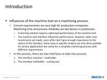
Introduction Influences of the machine tool on a machining process • Current requirements are very high for production companies. Machining time and process reliability are key factors in production. – – A winning solution requires optimised performance of the machine tool. The machine tool interface influences performance. However, when new investments are made, users often don’t give enough importance to the choice of the interface. Some tests or specific analysis are only done partially for certain applications but rarely for a complete machining process with different requirements. In this...
Open the catalog to page 2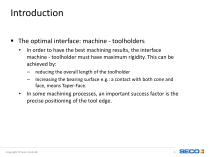
Introduction The optimal interface: machine - toolholders • In order to have the best machining results, the interface machine - toolholder must have maximum rigidity. This can be achieved by: – – reducing the overall length of the toolholder Increasing the bearing surface e.g.: a contact with both cone and face, means Taper-Face. In some machining processes, an important success factor is the precise positioning of the tool edge.
Open the catalog to page 3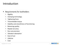
Introduction Requirements for toolholders • • • • • • • • • • • • Rigidity Clamping technology Tightening force Transmittable torque Stability and smoothness of functioning Balancing quality Repeat accuracy Run-out precision Vibration absorption Ease of use Lifetime Cost
Open the catalog to page 4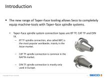
Introduction The new range of Taper-Face tooling allows Seco to completely equip machine-tools with Taper-face spindle systems. • Taper-Face spindle system connection types are BT TF, CAT TF and DIN TF. – BT TF spindle connection, also called BBT, is the most popular worldwide, mainly in the Asian market. CAT TF spindle connection is common in the NAFTA market. DIN TF spindle connection is mostly only used in Europe.
Open the catalog to page 5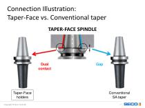
Connection Illustration: Taper-Face vs. Conventional taper TAPER-FACE SPINDLE Dual contact Taper-Face holders Copyright © Seco Tools AB
Open the catalog to page 7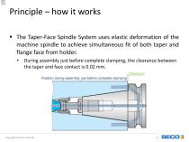
Principle – how it works The Taper-Face Spindle System uses elastic deformation of the machine spindle to achieve simultaneous fit of both taper and flange face from holder. • During assembly just before complete clamping, the clearance between the taper and face contact is 0.02 mm. Copyright © Seco Tools A
Open the catalog to page 8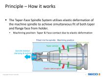
Principle – How it works The Taper-Face Spindle System utilises elastic deformation of the machine spindle to achieve simultaneous fit of both taper and flange face from holder. • Machining position: Taper & Face contact due to elastic deformation Copyright © Seco Tools A
Open the catalog to page 9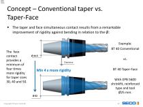
Concept – Conventional taper vs. Taper-Face The taper and face simultaneous contact results from a remarkable improvement of rigidity against bending in relation to the Ø: The face contact provides a minimum of four times more rigidity for taper sizes 30, 40 and 50. BT 40 Taper-Face With EPB 5600 shrinkfit, reinforced type and tool Ø25 mm. Copyright © Seco Tools
Open the catalog to page 10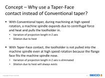
Concept – Why use a Taper-Face contact instead of Conventional taper? With Conventional taper, during machining at high speed rotation, a machine spindle expands due to centrifugal force and heat and pulls the toolholder in. • • Variation of projection length in Z axis Dilation due to heat With Taper-Face contact, the toolholder is not pulled into the machine spindle even at high speed rotation because the flange face fits the machine spindle nose. • • Variation of projection length in Z axis is eliminated Dilation due to heat will always exists
Open the catalog to page 11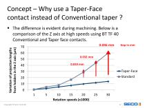
Concept – Why use a Taper-Face contact instead of Conventional taper ? Variation of projection lengths from holders in the Z axis (µm) The difference is evident during machining. Below is a comparison of the Z axis at high speeds using BT TF 40 Conventional and Taper face contacts. 0.046 mm Copyright © Seco Tools AB
Open the catalog to page 12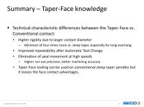
Summary – Taper-Face knowledge Technical characteristic differences between the Taper-Face vs. Conventional contact: • Higher rigidity due to larger contact diameter – Improved repeatability after Automatic Tool Change Elimination of axial movement at high speeds – Minimum of four times more vs. steep taper, especially for long overhang Higher run-out precision, better machining accuracy Taper-Face tooling can be used on conventional steep taper spindles but it looses the face contact advantages.
Open the catalog to page 13
PRODUCT RANGE – WORKPIECE SIDE TYPE
Open the catalog to page 14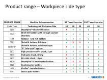
Product range – Workpiece side type PRODUCT RANGE Machine Side connection Code Type Technology at Workpiece Side Steadyline™ Shell mill holders Shell mill holders with through coolant channels Weldon - End mill holders Shrinkfit holders, DIN type Shrinkfit holders, reinforced type. "P" Safe-Lock™ system High precision collet chuck, 3 µm Hydraulic chuck, strong ER collet chuck, 10 µm Steadyline™ Combimaster holders Combimaster holders Graflex® modular holders Seco-Capto holders
Open the catalog to page 15
MARKET OVERVIEW
Open the catalog to page 16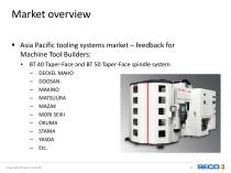
Market overview Asia Pacific tooling systems market – feedback for Machine Tool Builders: • BT 40 Taper-Face and BT 50 Taper-Face spindle system – – – – – – – – – – DECKEL MAHO DOOSAN MAKINO MATSUURA MAZAK MORI SEIKI OKUMA STAMA YASDA Etc.
Open the catalog to page 17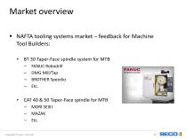
Market overview NAFTA tooling systems market – feedback for Machine Tool Builders: • BT 30 Taper-Face spindle system for MTB – – – – FANUC Robodrill DMG Mill/Tap BROTHER Speedio Etc. MORI SEIKI MAZAK Etc.
Open the catalog to page 18
MOUNTING POSSIBILITY
Open the catalog to page 19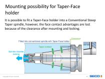
Mounting possibility for Taper-Face holder It is possible to fit a Taper-Face holder into a Conventional Steep Taper spindle, however, the face contact advantages are lost because of the clearance after mounting and locking. Copyright © Seco Tools AB
Open the catalog to page 20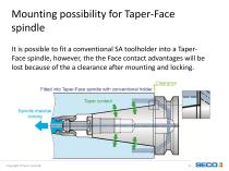
Mounting possibility for Taper-Face spindle It is possible to fit a conventional SA toolholder into a TaperFace spindle, however, the the Face contact advantages will be lost because of the a clearance after mounting and locking. Copyright © Seco Tools AB
Open the catalog to page 21All SECO TOOLS catalogs and technical brochures
 Solid End Mills.pdf
641 Pages
 Indexable Milling Catalog.pdf
856 Pages
 GL25-HEADS RANGE EXPANSION
13 Pages
 SECO NEWS SUMMARY 2019.1
9 Pages
 DOUBLE OCTOMILL™
2 Pages
 PRODUCT SUMMARY
2 Pages
 SECO NEWS SUMMARY 2018.1
14 Pages
 POZVÁNKA ZD KOVOSVIT
1 Page
 Machinability_poster
1 Page
 SQUARE T4
2 Pages
 SECO Product summary
2 Pages
 SECO NEWS
310 Pages
 DURATOMICTM
16 Pages
 QUATTROMILL-AL™
2 Pages


Archived catalogs
 DISC MILLING
36 Pages


- KENNAMETAL aeronautic milling cutter
- KENNAMETAL metal milling cutter
- Aeronautic drill bit
- Solid drill bit
- Metal drill bit
- Carbide milling cutter
- Diamond milling cutter
- Carbide drill bit
- PCD milling cutter
- Composite milling cutter
- Milling cutter for the aerospace industry
- Insert milling cutter
- Angle milling cutter
- KENNAMETAL aluminum milling cutter
- Steel milling cutter
- Aeronautic chuck
- Finishing milling cutter
- Diamond drill bit
- Composite drill bit