- Catalogs
- Rosen Aviation
- technical manual
technical manual

technical manual
This technical manual by Rosen Aviation provides comprehensive instructions for installing high-definition arm-mounted displays in aircraft cabins. It is intended for trained personnel and does not cover standard-definition models.
The displays support high-definition video inputs, including 3G HD-SDI up to 1080p and Composite (CVBS). They can switch between SDI and Composite inputs but cannot support both simultaneously. RS-232 control is available if configured.
Displays are integrated into cabin entertainment systems using SDI for video distribution, connecting multiple monitors to a video source.
Displays are mounted on arms with specific installation mechanisms. Proper orientation is crucial to avoid forced connections. Bases can be mounted on vertical or horizontal surfaces, with shielded harnesses recommended for better EMI performance.
Touch controls and on-screen display options allow users to adjust settings like backlight and aspect ratio. Advanced technician menus provide additional configuration options.
Includes tension adjustments and cleaning instructions. Displays meet RTCA DO-160F qualifications.
Troubleshooting guidance and contact information for technical support are provided.
Details on supported resolutions for Composite and SDI inputs are included.
Glossary of terms and a record of document revisions are provided.
This document provides technical specifications and operational procedures for Rosen Aviation's personal display systems, focusing on installation, power-up, and user interface controls.
Outlines mounting dimensions for various base receptacles and pinout connections for integrating the display with an aircraft's entertainment system. Emphasizes that the display is for entertainment purposes only and should be connected to a non-critical power bus.
Instructions include ensuring low impedance ground connections, connecting power supply and video source, and verifying the display's auto-on feature. Advises against connecting or disconnecting the display while power is applied.
Involves setting the limit switch to ensure the display turns off when stowed and managing the power harness to prevent stretching or kinking.
Features touch-sense buttons for operation, with layout varying by model. Users navigate options using plus and minus buttons.
Provides menu options for screen settings and informational readouts. The OSD automatically closes after a preset timeout period.
Includes options for adjusting backlight intensity, aspect ratio, and color schemes. Aspect ratio settings affect how the source video is displayed.
Allows fine-tuning of color and picture quality, including brightness, contrast, saturation, hue, and sharpness. Users can reset schemes to default settings.
Accessible via a specific button sequence, providing advanced controls and settings, including factory reset and 3D comb filter options for composite signals.
Offers further controls for image adjustments and includes options like Factory Reset and 3D Comb Filter to enhance picture quality.
The document serves as a comprehensive guide for installing, configuring, and operating Rosen Aviation's personal displays, ensuring optimal performance and user experience.
Includes Automatic Gain Control for signal compensation, Power Mode settings, Mode Menu for SDI models, OSD Timeout settings, Splash Screen options, and Front Panel LED controls.
Instructions for tension adjustments and cleaning the display using alcohol-free solutions. Emphasizes the importance of using a multimeter for voltage verification.
Lists compliance categories for environmental and operational conditions.
Provides explanations for technical terms and outlines changes made in each document revision.
Catalog excerpts

ELECTRONIC REVISION CONTROLLED
Open the catalog to page 1
Rosen Aviation Personal Displays Technical Manual, Personal Displays © 2011–2014 by Rosen Aviation, LLC All Rights Reserved The information contained herein is proprietary to Rosen Aviation, LLC. No part of this publication may be reproduced, transmitted, transcribed, stored in a retrieval system, or translated into any language in any form by any means without the written authorization from Rosen Aviation, LLC, except as allowed under copyright laws. Disclaimer of Liability The information contained in this document is subject to change without notice. Because we are continuously improving and...
Open the catalog to page 2
Rosen Aviation Personal Displays Document Number: 104461 Template: 4.4.1.6FM2; Revision A; 12/06/12
Open the catalog to page 3
Rosen Aviation Personal Displays Document Number: 104461 Template: 4.4.1.6FM2; Revision A; 12/06/12
Open the catalog to page 4
Rosen Aviation Personal Displays 1. INTRODUCTION Rosen’s high-definition personal monitors are available in a range of sizes and mounting options that allow customers to configure a system that fits their aircraft’s cabin interior. This manual describes how to install arm-mounted personal displays onto your aircraft. It contains everything you need to know to install the base receptacles and connect the display to confirm that it is functioning correctly. This manual covers only Rosen’s high-definition personal displays. Standard-definition displays are covered in the 9” Composite Technical Manual...
Open the catalog to page 5
Rosen Aviation Personal Displays 2. VIDEO INPUTS Rosen’s personal displays enable viewers to watch single, high-definition video signals in a variety of formats as well as standard video signals. The following video inputs are available on various models: Composite (CVBS) If the base receptacle is pinned out for SDI and Composite, then the corresponding display supports both video inputs. However, the display cannot support both video inputs simultaneously. If neither SDI nor COMPOSITE is connected, the display will default to SDI. If SDI is connected and no COMPOSITE is available, the display...
Open the catalog to page 6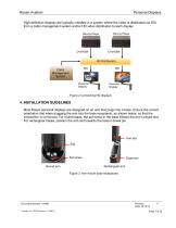
Rosen Aviation Personal Displays High-definition displays are typically installed in a system where the video is distributed via SDI from a cabin management system and/or HD video distribution to each display. Blu-ray Player Blu-ray Player Personal Display Personal Display Cabin Management System Figure 2 Connecting HD displays 4. INSTALLATION GUIDELINES Most Rosen personal displays are designed on an arm that plugs into a base. Ensure the correct orientation that when plugging the arm into the base receptacle, as shown below, so that the connection is not forced. For round bases, the set screw...
Open the catalog to page 7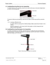
Rosen Aviation Personal Displays 4.1. Installing/Removing SlimLine Arm Assemblies To install a SlimLine arm assembly, press the arm button all the way in and push straight down on the arm into the plug body. Arm button Plug body Figure 4 SlimLine locking arm feature To remove a SlimLine arm assembly, press the arm button in all the way and lift up under the arm. 4.1.1. Locking a SlimLine Arm To rotate a SlimLine locking arm so that the display rotates, press the arm button in only halfway. Rotate the display/arm until it locks into the next position, and then release the arm button to lock in...
Open the catalog to page 8
Rosen Aviation Personal Displays 4.2.1. Locking a Rectangular Arm To rotate a rectangular arm so that the display rotates, press on the arm cap cover to rotate the arm and lock into place at 0° and 180° locations, and then release the cap cover. Arm cap cover Figure 6 Locking mechanism on a rectangular arm 4.2.2. In-seat Displays USE CAUTION when stowing or deploying the in-seat displays. The power turns on and off automatically when you raise and lower the display. To deploy and stow the display, press straight down on the latch button and gently guide the display up or down into a locked position....
Open the catalog to page 9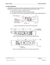
Rosen Aviation Personal Displays 4.3. Base Installations The bases mount on either a vertical or a horizontal surface, typically with a minimum of four screws (two per flange); however, the rectangular bases require only two screws. A ground wire is present in all base harnesses For base pinout information, refer to the monitor drawings We suggest connecting bases using shielded harnesses to improve EMI performance. Attach a grounding strap to the stud on the 0100-342 base receptacle Figure 8 Mounting dimensions for the 0100-342 base receptacle Figure 9 mounting dimensions for the 0100-140...
Open the catalog to page 10
Rosen Aviation Personal Displays Figure 11 Mounting dimensions for the 0100-043 base receptacle Figure 12 Mounting dimensions for the 0100-010 base receptacle Figure 13 Mounting dimensions for the 0100-004 base receptacle Document Number: 104461 Template: 4.4.1.6FM2; Revision A; 12/06/12
Open the catalog to page 11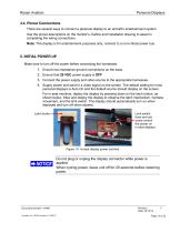
Rosen Aviation Personal Displays 4.4. Pinout Connections There are several ways to connect a personal display to an aircraft’s entertainment system. Use the pinout descriptions on the monitor’s Outline and Installation drawing to assist in completing the wiring connections. Note: This display is for entertainment purposes only; connect to a non-critical power bus. 5. INITIAL POWER UP Make sure to turn off the power before connecting the harnesses. Ensure low impedance ground connections on the base. Ensure that 28 VDC power supply is OFF Connect the power supply and video source to the appropriate...
Open the catalog to page 12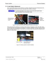
Rosen Aviation Personal Displays 5.1. In-seat Display Adjustments If an in-seat display does not shut off when it is stowed, adjust the set screw directly above the limit switch lever so that the limit switch activates when monitor is stowed. To prevent damage to the switch, be sure the limit switch lever does not bottom out on the switch body. Proper contact for the limit switch lever Adjust set screw to contact limit switch Figure 15 Set screw and limit switch positions for power on/off control If the power harness stretches or is kinking while stowing or deploying, loosen the cable clamp,...
Open the catalog to page 13All Rosen Aviation catalogs and technical brochures
 catalog 2011
20 Pages
 42" HD Bulkhead Display
2 Pages
 32" HD Bulkhead Display
2 Pages
 26" HD Bulkhead Display
2 Pages
 9" WS
9" WS3 Pages