- Catalogs
- ROHDE & SCHWARZ GMBH & CO. KG
- R&S®FS-K40
R&S®FS-K40

R&S®FS-K40
- Editable sweep settings including measurement range, resolution bandwidths, filter types, averaging, and smoothing factors.
- Fast residual FM/ϕM measurements over a settable frequency range.
- Simultaneous display of up to three traces and storage of results and settings.
- Remote control via GPIB or LAN.
- Frequency range varies by model, from 20 Hz to 50 GHz.
- Lower offset limit for FSU/FSQ/FSMR models is 1 Hz, and for FSP models is 10 Hz.
- Upper offset limit for all models is 1 GHz.
- Measurement accuracy is determined by the analyzer's characteristics.
- High phase noise measurement speed with trade-offs between speed and accuracy.
- User-definable carrier offset frequency range from 1 Hz to 1 GHz.
- Predefined sweep settings (Fast, Normal, Averaged) for ease of use.
- Autoscaling or user-defined x- and y-axis ranges.
- Trace smoothing options and evaluation lines for residual FM/ϕM measurements.
Catalog excerpts
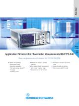
Data sheet Application Firmware for Phase Noise Measurements R&S®FS-K40Phase noise measurements with Analyzers R&S®FSP/FSU/FSQ/FSMR ♦ Editable sweep settings: -Measurement range -Resolution bandwidths -Filter types (analog, digital, FFT) -Averaging -Smoothing factors ♦ Editable limit lines with pass/fail indication ♦ Fast residual FM/q>M measurements over settable frequency range ♦ Comprehensive marker functions ♦ Simultaneous display of up to three traces ♦ Storage of results and settings ♦ Remote control via GPIB or LAN
Open the catalog to page 1
Application Firmware R&S®FS-K40 adds phase noise measurement capability to the Analyzers R&S®FSP/R&S®FSU/ R&S®FSQ/R&S®FSMR. Due to their very low inherent phase noise and low noise factor, the R&S®FSU, R&S®FSQ and the R&S®FSMR are ideal for applications that call for very high spectral purity, for example analyzing signal sources such as radio frequency chips used in the modern 3GPP communications standards. The high phase noise measurement speed is achieved through the high sweep rates of the Rohde & Schwarz analyzers. It is possible to trade off speed against accuracy at small resolution bandwidths...
Open the catalog to page 2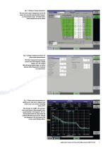
Fig. 1: Setting of sweep parameters: The area with a green background on the left shows the currently selected offset frequency measurement range. The fields with a white background can be edited. Fig. 2: Setting of global parameters for phase noise measurements: The basic measurement parameters (carrier level and frequency, display ranges, etc), the residual FM/ϕM measurement range, as well as discrete offset frequencies of interest are entered here. Fig. 3: Phase noise measurement of a signal source: blue trace: original trace; yellow trace: trace with a smoothing factor of 5%. The red trace...
Open the catalog to page 3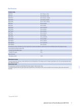
The maximum number of decades that can be represented in a phase noise diagram is determined by the user-definable carrier offset frequency range. Lower offset limit (inherent residual FM) Measurement accuracy The level measurement accuracy is mainly determined by the characteristics of the analyzer used. For relevant specifications refer to the corresponding data sheet (see "Related data sheets"). Inherent phase noise The measurement sensitivity is mainly determined by the analyzer's inherent phase noise. The diagrams opposite show the typical phase noise characteristics of the analyzers, which...
Open the catalog to page 4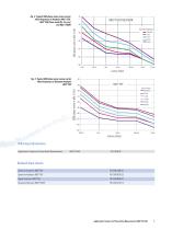
Fig. 4: Typical SSB phase noise versus carrier offset frequency of Analyzers ¸FSU, ¸FSQ (from serial No. 2xx xxx) and ¸FSMR ¸FSU/FSQ/FSMR SSB phase noise in dBc (1 Hz) Carrier offset Fig. 5: Typical SSB phase noise versus carrier offset frequency of Spectrum Analyzer ¸FSP Carrier offset Ordering information Application Firmware for Phase Noise Measurements Related data sheets Spectrum Analyzers ¸FSP Spectrum Analyzers ¸FSU Signal Analyzers ¸FSQ Measuring Receiver ¸FSMR Application Firmwa
Open the catalog to page 5
Certified Environmental System More information at www.rohde-schwarz.com (search term: FSP/FSU/FSQ/FSMR/FS-K40) Europe: Tel. +49 1805 12 4242, e-mail: [email protected] North America: Tel. 888 837 87 72, option 2 (from within the USA and Canada), +1 410-910-7800, option 2 (from other countries), e-mail: [email protected] Asia: Tel. +65 68463710, e-mail: [email protected] ¸is a registered trademark of Rohde & Schwarz GmbH & Co. KG · Trade names are trademarks of the owners · Printed in Germany (Pe as) PD0758.2631.32 · ¸FS-K40 · Version...
Open the catalog to page 6All ROHDE & SCHWARZ GMBH & CO. KG catalogs and technical brochures
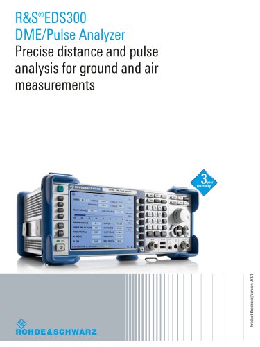 R&S®EDS300
12 Pages
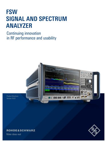 FSW
FSW32 Pages
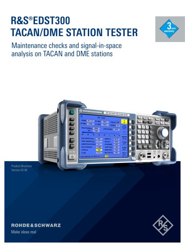 R&S®EDST300
12 Pages
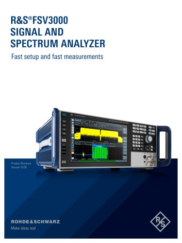 R&S®FSV3000
18 Pages
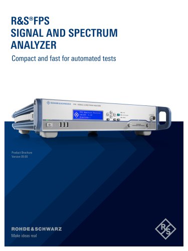 R&S®FPS
20 Pages
 R&S®RTP
46 Pages
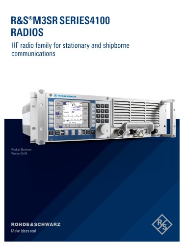 R&S®M3SR SERIES4100
34 Pages
 R&S®Series4200
24 Pages
 Oscilloscope innovation
7 Pages
 Signal and Spectrum Analyzers
40 Pages
Archived catalogs
 R&S®EVS300 ILS/VOR Analyzer
16 Pages
 R&S®M3AR MR6000R/L
4 Pages
 R&S®FSMR Measuring Receiver
14 Pages
 R&S®FS-K15 VOR/ILS
4 Pages
 HM8012 4¾-Digit–Multimeter
2 Pages
 Digital Multimeter HMC8012
3 Pages
 R&S®CLIPSTER
6 Pages
 IMF Mastering
4 Pages
 CMA180
24 Pages
 RTO2000
48 Pages


- Real-time software
- Airport scanner
- Aircraft antenna
- X-ray scanner
- Tester
- Aeronautical tester
- Audio panel
- Test software
- Avionics tester
- Measurement software
- ROHDE & SCHWARZ aeronautic analyzer
- Broadband antenna
- VHF audio panel
- Walk-through detector
- ROHDE & SCHWARZ benchtop analyzer
- Airport walk-through detector
- Passenger scanner
- Body scanner