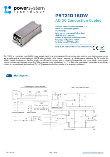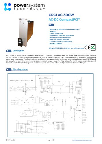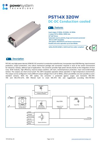
Catalog excerpts

DC-DC conduction cooled from 50W to several kWs 412, 24, 48, 72, 110Vdc IN 43 packages up to 150W, 300W, 500W 4Output from 3V3 to 48Vdc 4Input filtering EN55022 & transient protection 4Reverse polarity protection 4Several outputs, parallel or series operations up to several kWs 4MIL COTS options MIL STD1275, 461, 810, 704 Safety IEC/EN 60950-1, RoHS lead-free-solder compliant RoHS Description The PST14, very compact DC-DC converter in chassis mount format, incorporates input filtering, input and output protections, very robust mechanical mounting and connection, optional conformal coating, required in most of the severe environment for industrial, railways, defense type of applications. The converter provides high reliability thanks to the integration of Vicor Corp. modules, high efficiency, input-to-output isolation, soft start, overtemperature protection, input over/undervoltage lockout. The converters wide range of inputs are protected against surges and transients and EMI filtered. The outputs are countinuously short-circuit proof .The 100°C baseplate operation allows operation in high temperature environment. The output can be configured in many different output voltages from 3V3 to 48Vdc, can be put in series and parallel, others possibilities are even possible as semi-standard versions. Wide range of accessories (see page 16) like input & output Bus bars, N+1 oring diodes, parallel cables are available to simplify multi units assemblies. Military options (M) make it suitable for MIL STD compliance. J11 INH+ Active transient protection (M option)
Open the catalog to page 1
Options Description Heatsink (H) The PST14 is built as standard with a aluminum baseplate as described in the mechanical data. The converter can be delivered with a 15mm height heatsink with longitudinal fins (-H) or transversal fins (-H1). See page 15 for mechanical drawings. 3D models available on the web site. In case of using H or H1 option, the thermal impedance (Rth) of the heatsink mentioned below must be considered for the airflow or maximum power calculation. Conditions : 55°C ambiant, convection (0m/s vertical mounting) and 2m/s airflow: PST14A -H or H1: Rth@0m/s: 1,8°C/W,...
Open the catalog to page 2
OutputElectrical Output Data PST14A General conditions : 25°C ambiant. 1) Adjustment below -10% possible as semi-standard versions , consult factory -2) Recycle input voltage or inhibit to restart (>100ms off) - 3) Output voltage 95 % of nominal - 4) Output voltage < 250mV - 5) Nominal input, full load, 20MHz bandwidth - 6) No load to full load, nominal input
Open the catalog to page 3
Electrical Output Data PST14B General conditions : 25°C ambiant. 1) Adjustment below -10% possible as semi-standard versions , consult factory -2) Recycle input voltage or inhibit to restart (>100ms off) - 3) Output voltage 95 % of nominal - 4) Output voltage < 250mV - 5) Nominal input, full load, 20MHz bandwidth - 6) No load to full load, nominal input
Open the catalog to page 4
Electrical Output Data PST14C General conditions : 25°C ambiant. 1) Adjustment below -10% possible as semi-standard versions , consult factory -2) Recycle input voltage or inhibit to restart (>100ms off) - 3) Output voltage 95 % of nominal - 4) Output voltage < 250mV - 5) Nominal input, full load, 20MHz bandwidth - 6) No load to full load, nominal input
Open the catalog to page 5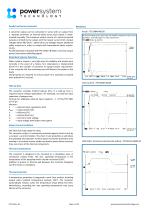
Parallel and Series Connection A converter output can be connected in series with an output from a separate converter, an internal diode across each output is implemented internally. The maximum output current of a serial-connected outputs is limited by the output with the lowest current limit. Output voltages above 48V (SELV - Safety Extra Low Voltage) require additional safety measures in order to comply with international safety requirements. Parallel operation is possible with PST14 Mini & Maxi to increase output power (see below parallelling signal). Inrush : PST14B48-48250 No inrush...
Open the catalog to page 6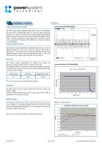
Auxiliary Functions Waveforms Output Noise (PST14B48-48250) Primary Inhibit (Remote On/Off) The inhibit input disables (logic low, pull down or short circuit between INH- and -IN) or enables (logic high TTL, pull up or open-circuit) the converter. This signal is referenced to the input voltage and will disable/ enable all outputs at the same time when inhibition & parallel cable is used. In systems consisting of several converters, this feature may be used to sequence the activation of the different converters if inhibition is used separately. Output Voltage Adjustment The converter output...
Open the catalog to page 7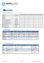
Environmental Functionalities and compliance table Input 12V Parallel operation current share with PR connected R option or external diode Conformal coating MIL-STD-704 A,C,D,E,F, 28V Steady State M option, built to meet MIL-STD-704 A,C,D,E,F 28V Surges High Transients MIL-STD-704 A,C,D,E,F 28V Surges Low Transients M option, built to meet M option, built to meet Series operation Remote senses MIL COTS version MIL-STD-704 C,D,E,F 28V Surges Low Transients M option, built to meet Redundant operation M option, built to meet M,V option built to meet M option built to meet M option built to...
Open the catalog to page 8
Electromagnetic Electromagnetic Emissions PST14A Level according to EN55022A, peak detector, average limit, PST14A24-24400, 400W
Open the catalog to page 9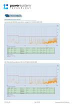
Electromagnetic Electromagnetic Emissions PST14B Level according to EN55022A, peak detector, average limit, PST14B28-12200, 200W
Open the catalog to page 10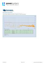
Electromagnetic Electromagnetic Emissions PST14C Level according to EN55022A, peak detector, average limit, PST14C24-12100, 100W
Open the catalog to page 11
Installations Instructions Cleaning Agents and Process These converters are components, intended exclusively for integration into other equipment by an industrial assembly process or by a profes-sionnaly competent person. Installation must strictly follow the safety regulations in respect of the enclosure, mounting, creepage and clearance distances, markings of the end-use application. Connection to the system shall be made via appropriate connection. The +Vin is internally fused. This fuse is designed to protect the converter against overcurrent caused by a failure, but may not be able to...
Open the catalog to page 13All POWER SYSTEM TECHNOLOGY catalogs and technical brochures
-
PST21D
11 Pages
-
CPCI AC 300W
9 Pages
-
PST14X 320W
12 Pages
-
PST21A
13 Pages


