- Catalogs
- OPEN MIND TECHNOLOGIES AG
- hyperCAD®-S.
hyperCAD®-S.

hyperCAD®-S.
Open Mind Technologies AG has introduced hyperCAD®-S, a CAD system specifically designed for CAM programmers. It integrates with hyperMILL® and features a unique 3D CAD kernel, providing an intuitive and efficient solution for NC programming processes.
- CAD for CAM: Designed to meet CAM users' needs, focusing on efficient programming.
- 64-bit Multi-application: Supports multiple documents and models simultaneously.
- Intuitive Operation: Features a user-friendly interface with self-explanatory icons.
- Data Exchange: Offers comprehensive import and export interfaces for various formats.
hyperCAD®-S provides advanced geometric manipulation tools, including smart selection mechanisms and customizable filter functions, to streamline the programming process.
The Solids module allows direct modelling capabilities, enabling users to modify solid models without a history tree, simplifying the process for CAM programmers.
hyperCAD®-S Mesh includes functionalities for preparing scanned data for milling, ensuring high-quality results.
This module supports targeted deformation of geometries, enabling complex shape creation and compensation for manufacturing variations.
The hyperCAD®-S Viewer and hyperMILL® SHOP Viewer enhance process reliability and communication by allowing users to view and simulate CAD and CAM data.
hyperCAD®-S is a comprehensive CAD system that enhances the efficiency and effectiveness of CAM programming, tailored to the specific needs of CAM users.
hyperMILL® is seamlessly integrated into hyperCAD®-S, enhancing speed and efficiency, allowing direct access to CAD functions.
- Intelligent Functions: Includes stock tracking, job linking, and automatic collision avoidance.
- Direct Measuring: Enables direct measuring on toolpaths and stock models.
- Efficient Workflows: Features associative programming and automatic operations via API.
- Structured CAM Projects: Offers a unified interface for CAD and CAM functions.
hyperMILL® provides comprehensive machine and material removal simulation, supporting various machining strategies.
Utilizes cutting-edge CAM technologies for standardization and automation.
Offers a flexible tool database that synchronizes with other systems.
Generates programs optimized for specific machines and components.
OPEN MIND Technologies AG operates worldwide, providing comprehensive support across various regions.
Catalog excerpts

© The helmet was programmed and produced by DAISHIN
Open the catalog to page 1
In a class of its own among CAD systems Only a high-end CAM developer can do CAD for CAM. With this in mind, Open Mind Technologies AG – known as an innovative pioneer – developed a new CAD system from scratch that is perfectly matched to hyperMILL . The system has its own 3D CAD kernel from OPEN MIND. The result is a unique CAD system ® for CAM programmers that is very easy to learn and that vastly accelerates NC programming processes. hyperCAD -S fully exploits the performance offered by contemporary hardware systems to create ® digital manufacturing data. The advanced and extremely powerful...
Open the catalog to page 2
CAD for CAM CAM programmers use CAD systems differently from most engineers and designers. hyperCAD®-S is therefore designed entirely to meet the demands of CAM users. Efficient CAM programming is of primary importance and perfectly supported by the CAD system. “At last we’ve got a CAD system for CAM programmers!” Stefan Nagel, Deputy Managing Director of Kiefer Werkzeug- und Vorrichtungsbau, Pfullingen Keyword navigation: Graphic entities can be linked using tags, similar to keywords. This makes it easy to filter all the infor ation m about the CAD model. For example: ‘All faces with a radius...
Open the catalog to page 3
Every CAM programmer is familiar with the standard CAD tasks of selecting, adding, deleting, modifying, showing and hiding faces, curves and points. Users expect top-quality results from the ruled, filling and offset faces that they create. hyperCAD®-S offers all this and much more. OPEN MIND took great care when developing the CAD innovation to adapt the range of CAD functions to meet the real needs of CAM programmers rather than designers. Instead of relying on numerous distributed submenus (as is the case in conventional design systems), hyperCAD®-S uses central, user-friendly dialogues with...
Open the catalog to page 4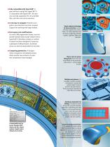
■ Fully compatible with hyperCAD®: It goes without saying that hyperCAD®-S is compatible with hyperCAD®. All versions are fully supported: E3, E2 and GKD files, job lists and entity selection. ■ A new way to navigate: Powerful navigation and selection functions provide support for working with large models. ■ Fast repairs and modifications: As every CAM programmer knows, most imported external data records contain errors. hyperCAD®-S therefore contains a number of repair functions designed to speed up subsequent CAM processes. Geometry areas can also be easily edited at any time. ■ Comparing...
Open the catalog to page 5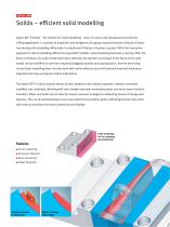
Solids – efficient solid modelling hyperCAD -S Solids – the module for solid modelling – was, of course, also developed primarily for ® CAM programmers. In contrast to engineers and designers, this group requires features without a history tree during solid modelling. Why make it complicated if doing it directly is quicker? With the innovative approach to direct modelling offered by hyperCAD -S Solids, solid modelling becomes a real joy: After the ® faces or features of a solid model have been selected, the position and shape of the faces of the solid model can be modified in real time simply...
Open the catalog to page 6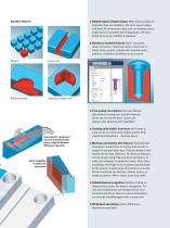
Standard features Time-saving zone feature: The zone feature also allows creating user-specific features. Zones can be transformed, copied, deleted or also selected with hyperMILL . Linear slot Rotational slot Numerous standard features: Basic structures, linear extrusions, rotational solids, linear and rotation slots, pockets, simple and complex holes, patterns, chamfers and fillets can be created. Reliable import of external data: When external data are imported, they are handled in the same way as native CAD data. All construction data, such as sketches, faces, single parts or complete machining...
Open the catalog to page 7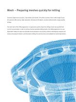
Mesh – Preparing meshes quickly for milling Scanned, forged and cast parts, clay models and moulds: 3D surface scanners have a wide range of uses. 3D scanners offer precise, high-resolution, full views of 3D objects, mostly combined with a large quantity of data. The main task of the CAM programmer is to generate a perfect basis for milling a mesh very quickly from a set of scanned data. In order to achieve the best possible milling results, the CAM programmer can use hyperCAD®-S Mesh to repair any possible mesh deviations very quickly, perform metrological analyses and checks and prepare meshes...
Open the catalog to page 8
■ Smooth meshes This function allows the user to smooth meshes in order to repair deviations. ■ Decimate meshes This function allows the user to reduce the mesh density while retaining the geometry properties. The reduced data volume helps to accelerate the model calculation. ■ Fill mesh areas This provides a simple and convenient way to close holes in meshes. ■ Separate mesh clusters This function allows the user to delete meshes that are not connected. ■ Mesh from faces A mesh can be generated from faces, open and closed solids. ■ Split meshes Mesh elements can be split using a planar entity....
Open the catalog to page 9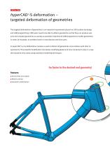
hyperCAD -S deformation – targeted deformation of geometries ® The targeted deformation of geometries is an important requirement placed on CAD systems by design and CAM programming. CAM users need to be able to deform geometries so that they can produce variants and complex geometries as quickly as possible. Experienced CAM programmers modify geometries in order, for example, to overbend tools or manufacture precision parts. In hyperCAD -S, the Deformation module is used to deform all geometries in accordance with their re® quirements. This powerful modification tool allows modifying global...
Open the catalog to page 10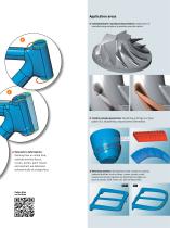
Application areas n Compensating for manufacturing variations: Application of manufacturing variations to produce precision parts. n Creating complex geometries: Transferring a 2D logo or a tread pattern to a 3D geometry using volumetric deformation. Volumetric deformation: Starting from an initial face, selected entities (faces, curves, points, point clouds and meshes) are deformed volumetrically to a target face. n Deforming entities: Starting from start contours or points, selected entities such as faces, curves, points, point clouds and meshes (green) are deformed to target contours or points...
Open the catalog to page 11All OPEN MIND TECHNOLOGIES AG catalogs and technical brochures
 Volkswagen, Braunschweig
2 Pages
 Tml Precision Engineering
3 Pages
 Flexible Machining Systems
2 Pages
 Polygona
3 Pages
 SOFTWARE
5 Pages
 hyperMILL
8 Pages
 hyperMILL®. Version 2017.1.
16 Pages
 hyperMILL®. Version 2016.2
16 Pages