LH050

LH050
- Impact and Damage Protocol: After an impact, the helmet shell must be destroyed and replaced as it is designed for single-impact protection.
- Inspection Requirements: Inspect for dents, cracks, deformation, gel coat damage, impact cap movement, and damage to visors and chinstraps. Record all inspections.
- Responsibilities: Users and maintenance units must report impacts. MSA is not liable for unreported damage. Only MSA distributors can remove the impact cap.
- Replacement Criteria: Replace the shell if aramid fibers are damaged or if the fall height exceeds 1 meter. Replace defective rail and chinstrap mounts, rebond edge seals if necessary, and replace the impact cap if unstuck or if the rim shows white marks.
- Inner Visor Assembly: Replace parts with excessive paint spots or scratches and ensure smooth visor rotation.
- Chinstrap Assembly: Replace if there is play in the locking clip, cracks, defective stitching, or wear in the strap or loop.
Catalog excerpts

Maintenance manual MAINTENANCE MANUAL FLIGHT HELMET LH 050
Open the catalog to page 1
Maintenance manual Page Table of Contents - Warning notice - Helmet description 2 – Inner liner elements 6 – Microphone unit and cover (standard or winchman's) 7 – Mixed microphone boom 9 – Removing the complete microphone 10 – Earphones and hygiene parts of the ear cups Servicing and maintenance table Inspection table and replacement criteria Appendices: Replacement criteria MSA, Châtillon sur Chalaronne • Tél. +33 (0)474 55 01 55 • E-mail i
Open the catalog to page 2
Maintenance manual WARNING NOTICE Thank you for putting your trust in MSA products. Read these instructions carefully before using your helmet. Failure to follow these instructions could reduce the level of protection provided by your helmet. The level of protection provided by the helmet is only guaranteed if it has all the original MSA parts. Therefore, any modifications made to your helmet or the absence of any of the parts forming the original helmet will make the equipment supplied non-compliant, releasing MSA from all liability. In order to keep improving its products, MSA reserves the...
Open the catalog to page 3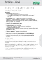
Maintenance manual FLIGHT HELMET LH 050 HELMET DESCRIPTION Description: • The shell of the helmet consists of: - an outer shell made from high performance composites, - an expanded polystyrene impact cap to absorb shocks, covered with an inner liner. • The inner liner consists of a T-shaped comfort liner and a neck pad. The helmet is adapted to the shape of the wearer's head by personalising the T-shaped comfort liner and the neck pad and the adjustment pads for adjusting the pressure of the ear cups on the ears. The helmet has 1 inner protective visor. The ear protection system consists of:...
Open the catalog to page 4
Maintenance manual INTRODUCTION Important: whenever you are handling the helmet, make sure you put it down on its carry bag. Tools required: - Flat screwdriver - Philips screwdriver MSA, Châtillon sur Chalaronne • Tél. +33 (0)474 55 01 55 • E-mail info.fr@MSAsafety.
Open the catalog to page 5
Maintenance manual 1. Chinstrap: Tools: Philips screwdriver. Dismantling duration: 15 seconds. Mounting duration: 30 seconds. The chinstrap is secured to the helmet by means of two screws on the left chinstrap bracket. To remove the chinstrap, unscrew the screws on the left side, then take out the chinstrap levers by holding them by the ends. To reinstall, engage each lever, making sure the chin cup is the right way round (the return part of the strap should be uppermost) and so are the levers. Lock by pressing in the middle of the lever. Tighten the 2 screws. You do not have to remove the chinstrap...
Open the catalog to page 6
Maintenance manual 2. Inner liner elements: Tools: None. Dismantling duration: 20 seconds. Mounting duration: 45 seconds. There are three inner liner elements: The comfort liner with its interchangeable foam pieces, each supplied in 3 thicknesses (4, 8 and 12 mm thick), The neck pad (XS, S and M or L, XL and XXL depending on the helmet size), The ear cups and their adjustment pads (3 on each side + 2 extra on each side), The comfort liner is adjustable in 4 areas with 3 possible thicknesses (N.B. When replacing the foam pieces, check that they are seated correctly). The neck pad is also supplied...
Open the catalog to page 7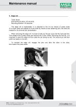
Maintenance manual 3. Edge roll Tools: None. Dismantling duration: 20 seconds. Mounting duration: 45 seconds. The edge roll is replaceable. It is attached to the rim by means of press studs (3 on each side) and adjusts to fit the shell by means of two fastening pins. No tools are needed for its removal and reinstallation. When removing the edge roll, it is best to take out the ear cups and the neck pad first. Then detach the 6 press studs and remove the 2 pins. When removing the first pin, it is important to twist the edge roll then slide the pin along its slot. The second pin will then come...
Open the catalog to page 8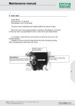
Maintenance manual 4. Inner visor: Tools: None. Removal time: 15 seconds. Reinstallation time: 30 seconds. The inner visor is attached to its rotation system by means of clips. Move the visor to the lowered position. Important: the direction of removal of the inner visor is perpendicular to the 2 rivets of the visor attachments. To reinstall it, check that the control levers of the inner visor are in the lowered position. Engage the visor so that the clips will go into their housings correctly. Clip in by pressing on the ends of the visor. Rotation system in lowered position Reinstallation: Insert...
Open the catalog to page 9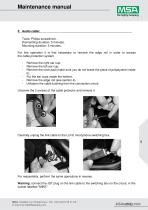
Maintenance manual 5. Audio cable: Tools: Philips screwdriver. Dismantling duration: 5 minutes. Mounting duration: 5 minutes. For this operation it is first necessary to remove the edge roll in order to access the cable protection system. - Remove the right ear cup, Remove the left ear cup, Remove the neck pad (make sure you do not break the piece of polystyrene inside it), Put the ear cups inside the helmet, Remove the edge roll (see section 4), Unfasten the cable bushing from the connection circuit. Unscrew the 2 screws of the cable protector and remove it Carefully unplug the link cable to...
Open the catalog to page 10
Maintenance manual 6. Microphone unit and cover (standard or winchman's): Tools: None. Dismantling duration: 15 seconds. Mounting duration: 30 seconds. To remove the standard microphone cover (foam and attachment ring): - Pull off the plastic ring (for the winchman's cover, pull off the cover itself). Cut out for microphone arm Remove the protective foam from the unit. Then pull off the microphone unit to separate it from its base. To reinstall it, engage the unit in its mount, making sure the foolproofing notches are the correct way round. Put on the cover followed by the ring, making sure the...
Open the catalog to page 11
Maintenance manual 7. Combined microphone boom: Tools: Philips screwdriver. Dismantling duration: 1 minute. Mounting duration: 1.5 minutes. The left ear cup needs to be removed and the 3 press studs on the left side of the edge roll should be undone. Unplug the microphone's JST connector. JST connector for connecting microphone JST connector linked to connection circuit Remove the grommet from the shell. Unscrew the central screw from the microphone boom. 11 Unscrew the microphone boom, making sure its components remain stacked in the correct order. For reassembly, perform the same operations...
Open the catalog to page 12All MSA catalogs and technical brochures
 LH250 Helmet
2 Pages
 LH 350 Helicopter Helmet
4 Pages
 LA100 Helmet
2 Pages