- Catalogs
- Mitutoyo Europe
- CMM Software
CMM Software

CMM Software
MCOSMOS is a modular data processing software for coordinate measuring machines (CMM), compatible with both manual and CNC types, operating under Windows XP. It features user-friendly interfaces with icons and pull-down menus.
MCOSMOS is available in versions for manual and CNC CMMs, supporting graphical display and interaction with measurement elements. Users can customize screen configurations for better usability.
The software includes modules like GEOPAK for geometric measurement, CAT1000S for 3D surface evaluation, CAT1000P for CAD-based programming, and SCANPAK for 2D profile evaluation. These modules can be added as needed.
MCOSMOS offers a multifunctional graphic display for real-time visualization of measurement results, allowing tolerance measurements and deviation calculations.
The Part Manager controls part programs and measurement procedures, featuring user login, program initiation, and process management.
GEOPAK operates in Single & Learn, Repeat, and Part Program Editor modes, with tools for probe data management, auto-calibration, and coordinate system setup.
The software provides flexible options for defining coordinate systems and measuring elements, with various calculation methods and measurement modes.
MCOSMOS offers comprehensive tools for CMM data processing, emphasizing ease of use and flexibility.
The document details measurement and tolerancing procedures using GEOPAK, focusing on geometric elements like points, lines, and circles. It includes instructions on result display, distance and angle calculations, and tolerance zone comparisons.
Elements that can be toleranced include points, lines, planes, circles, ellipses, cones, spheres, and cylinders, with specific items like coordinates and geometric properties.
Describes selecting measurement elements and displaying results, with examples of distance and angle calculations.
Involves comparing measured values with design values and tolerance limits, with results displayed in bar graph form.
Details procedures for straightness, parallelism, runout, coaxiality, orientation, and positional deviation tolerance zone measurements.
Guidance on setting CNC parameters like traverse speed and measuring speed for safe and accurate operation.
Describes the auto element measurement function, simplifying the process by eliminating the need for teaching or programming.
Explains creating and editing part programs using control statements for flexible measurement programs.
Options for outputting measurement results to printers or files, with graphic and voice output for guidance.
Details the process of performing one-point measurements and tolerancing with CAD data in real-time.
Describes software programs like CAT1000S, CAT1000P, SCANPAK, and GEARPAK for CAD data processing and measurement in manufacturing.
Lists supported CAD formats like IGES, SAT, and STEP, with specific version support.
Outlines procedures for loading CAD data, setting reference coordinates, and creating part programs from CAD models.
Highlights CAT1000S for evaluating free-form surfaces and SCANPAK for contour measurement.
Mentions compatibility with gear standards like ISO1328 and JIS B 1702, supporting automatic tolerance setting.
Suggests using the Best-Fit function and interference check functions to optimize measurement accuracy.
Features like mirror inversion, thick plate setup, and automatic tolerance setting support both online and offline operations.
Technical information on MeasureReport for inspection table generation and MeasurLink STATMeasure PLUS for statistical processing and process control.
Supports BMP-format files, macro settings for inspection tables, and generates tables using GEOPAK data.
Facilitates statistical processing and real-time control charts, requiring Microsoft Excel for full functionality.
Product information is approximate and subject to change, with export regulated under Japanese law.
Catalog excerpts
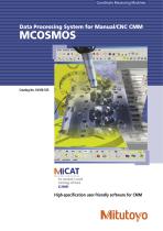
Coordinate Measuring Machines MiCAT Mitutoyo Intelligent Computer Aided Technology the standard in world metrology software cmm High-specification user-friendly software for CMM
Open the catalog to page 1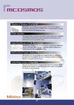
Adoption of Windows XP as the OS MCOSMOS is a new data processing program family for any type of coordinate measuring machine (CMM). This is a modular system running under the Windows XP operating system. Simple Operation This program does not need to use specific code numbers since it adheres to the Windows standards and allows measurement procedure to be selected from icons or pull-down menus. Supporting Manual and CNC Measurement MCOSMOS is available in two versions: one for a manual type CMM and one for a CNC type CMM. Both use a consistent mode of operation to handle manual or CNC measurement...
Open the catalog to page 2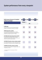
PartManager The control center from which the software package is initialized, and individual part programs are managed. GEOPAK (Geometry module) For (online/offline) part program creation, using the measurement of geometric elements. Extensive tolerance comparisons and output functions are included. CAT1000P (CAD based programming module) For (online/offline) part program creation, using the measurement of geometric elements directly from the CAD model, with automatic collision avoidance. CAT1000S (3D freeform surface evaluation module) CAD model based generation of surface measurement points, and...
Open the catalog to page 3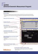
Elements Toolbar » A group of icons for measurement of point, line, plane, circle, ellipse, cone, sphere, cylinder, curve, curved surface, and gear elements. Click on the icon of an element to be measured to display a sub-window which allows you to change the number of input points, select a calculation formula, invoke an element from memory, combine multiple elements, calculate the point(s) of intersection of two elements, and so on. Emergency Stop Icon-- • Implements an emergency stop during CNC measurement. Probe Setting Icon • Provides optional functions such as probe replacement and stylus...
Open the catalog to page 4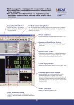
/liCAT Mitutoyo Intelligent Computer Aided Technology the standard in world metrology software cmm • Software program for universal geometric measurement of a workpiece. • This program allows measurement operation with the same operational feeling as Windows. • The program has achieved extraordinary ease of operation by a new method using toolbar/icon menus and totally without using any code or code number. Distance Calculation Toolbar • Performs calculation of a distance or an angle by specifying two elements that have been measured. Coordinate System Setting Toolbar • Sets up a coordinate system...
Open the catalog to page 5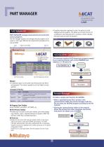
PART MANAGER • If graphics have been registered in parts, the parts list can be displayed with the graphics. This allows you to check the form of a workpiece to be measured next to a picture or photo. (Doubleclicking this picture starts the program.) PART MANAGER PART MANAGER manages measurement parts and starts various programs. The Part Manager registers and manages the part programs to be used on a CNC type CMM and the measurement procedures for a manual CMM. Login Program Start Toolbar Parts List ASCII-GEOPAK Converter This converter reads an ASCII-format part program created by an external...
Open the catalog to page 6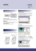
Three Measurement Modes Useful Probe Setting Functions GEOPAK has three modes of operation. ● Probe Data Manager Performs creation, edit (change), copy, delete, or storage of probe data and calibration (compensation of stylus ball center position and diameter by probing the master ball). A set of probe data that has been registered can easily be selected by highlighting that data set with the mouse. (See figure below.) ����������� ������������������� ● Single & Learn Mode Performs usual single-workpiece measurement. At this time the measurement procedures are stored as parts and available in the...
Open the catalog to page 7
● Coordinate System Definition Using the Separate Element Functions A part coordinate system can also be defined by combining coordinate system setting functions and element measurement functions. User-friendly Coordinate System Setting Sets up the coordinate system for a workpiece placed anywhere within the measuring volume. ● Coordinate System Definition Using a Predefined Element Sequence • Probing sequences using eight predefined combinations of typical workpiece elements are available to define the part coordinate system. The most appropriate sequence for any particular workpiece is invoked by...
Open the catalog to page 8
(2) Calculation formula selection This toolbar selects a calculation method for circle measurement from among the least squares, inscribed circle, circumscribed circle or minimum zone methods. (3) Element name An arbitrary name can be given to an element to be measured. (4) Memory number Specifies the memory location number for an element. (5) Number of input points The number of measurement input points is specified here. No limit is placed on the number of points. (The upper limit is dependent on computer performance.) (6) Unspecified number of input points If the number of measurement input points...
Open the catalog to page 9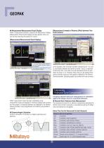
[Measurement Example of Distance (Pitch) between Two Circle Centers] ● Measurement/Measurement Result Display When a measurement element is selected, the Measurement Display (Measurement Point Number Display) window appears. Now, you can start by measuring the position of a point. [Measurement/Measurement Result Display] “1 - 4” in the window indicates “Measure (input) the first point of a total of 4 points to be measured.” The message can also be delivered through the voice guidance (option). In this example, after circle data has been collected (circle 1 to circle 3), the distance between the...
Open the catalog to page 10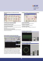
[Circle Element Tolerance Zone Measurement Setup Window] [Straightness Tolerance Zone Measurement Setup Window] (1) Tolerance zone measurement ON/OFF Click on the button of an item to be toleranced. (2) Design value/tolerance input Enter the design value and upper/lower tolerance limit for each item. (3) Fitting symbol specification Tolerancing can also be performed by giving a design value and type of fit symbol. (4) Extended tolerancing specification Select any of these buttons to output tolerancing data to MeasurLink (Statistical Processing Program). (1) Element identification Specifies an element...
Open the catalog to page 11All Mitutoyo Europe catalogs and technical brochures
 Vision Measuring Machines
40 Pages
 Contour & Surface Measurement
24 Pages
 Contour Measurement
16 Pages
 Coordinate Measuring Machines
32 Pages
- Aeronautical software
- Testing machine
- Aeronautical testing machine
- Measurement software
- Laser scanner
- Material testing machine
- Aeronautic laser scanner
- Non-contact laser scanner
- Flaw detector
- Aeronautic flaw detector
- Aeronautic surface profiler
- Automatic testing machine
- Optical coordinate measuring machine
- Vertical testing machine
- Measurement laser scanner
- Structure coordinate measuring machine
- CNC coordinate measuring machine
- Phased array flaw detector
- Mechanical coordinate measuring machine