
- Catalogs
- Mini-Circuits
- BDCH-20-63+

BDCH-20-63+
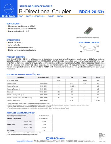
BDCH-20-63+
- Frequency Range: 2000 to 6000 MHz
- Mainline Loss: 0.15 to 0.30 dB
- Nominal Coupling: 20±1.5 dB
- Directivity: 15.5 to 19 dB
- Return Loss: 16 to 20 dB
- Thermal Resistance: 0.25 °C/W
- Operating Case Temperature: -55°C to +105°C
- Storage Temperature: -55°C to +105°C
- Power Input: 180W at +85°C, 130W at +95°C, 100W at +105°C
- DC Current: 2 A
- High power handling up to 180W
- Ultra wideband from 2000 to 6000 MHz
- Low insertion loss of 0.15 dB
Catalog excerpts
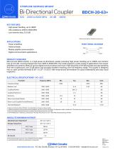
STRIPLINE SURFACE MOUNT KEY FEATURES FUNCTIONAL DIAGRAM • High power handling, up to 180W APPLICATIONS • Power amplifiers • Antenna feeds • Mobile satellite communication • Digital communication applications PRODUCT OVERVIEW Mini-Circuits' BDCH-20-63+ is a high-power bi-directional coupler providing high power handling up to 180W and mainline loss of 0.15 dB. Covering frequencies from 2000 to 6000 MHz, the model supports a wide variety of applications from power amplifiers and antenna feeds to various digital communications and more. High directivity of 19 dB provides accurate sampling from the coupled port, and 20 dB return loss provides excellent matching over full frequency range. The coupler is designed into an open printed laminate (0.56" x 0.20" x 0.051") with wrap-around terminations for good solderability and easy visual inspection. 1. Tested on Evaluation Board TB-864+. De-embedded to the device reference plane. 2. Model is symmetrical and all ports are interchangeable, see Port Function Description/Configuration table for details and S-Parameters for actual performance. 3. Does not include theoretical loss due to coupling. Nominal theoretical loss is 0.05 dB. 4. Thermal Resistance is defined as, example (®jc= (Hot Spot Temperature on DUT - Base Plate Temperature)/Input Power) ABSOLUTE MAXIMUM RATINGS5 Operating Case Temperature6 5. Permanent damage may occur if any of these limits are exceeded. 6. Case temperature is defined as temperature on base plate. www.minicircuits.com P.O. Box 350166, Brooklyn, NY 11235-0003 (718)934-4500 [email protected]
Open the catalog to page 1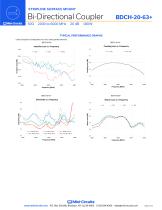
STRIPLINE SURFACE MOUNT TYPICAL PERFORMANCE GRAPHS * Data corresponds to Configuration A at +25°C unless specified otherwise. Insertion Loss vs. Frequency Coupling Loss vs. Frequency Return Loss vs. Frequency www.minicircuits.com GJ Mini-Circuits P.O. Box 350166, Brooklyn, NY 11235-0003 (718) 934-4500 [email protected]
Open the catalog to page 2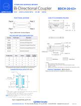
STRIPLINE SURFACE MOUNT FUNCTIONAL DIAGRAM Pad 4 Pad 3Pad 1 Pad 2 Figure 1. BDCH-20-63+ Functional Diagram CASE STYLE DRAWING (PQ2099) 7. Model is symmetrical and all ports are interchangeable, see Port Function Description/Configuration table for details and S-Parameters for actual performance. Solder Resist 1. Base material: Printed wiring laminate. 2. Termination finish: 2-5 pinch (.05-.13 microns) Immersion Gold. 4. Marking may contain other features or characters for internal lot control. *Marking may contain other features or characters for internal lot control. DENOTES COPPER LAND PATTERN...
Open the catalog to page 3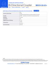
STRIPLINE SURFACE MOUNT CLICK HERE ADDITIONAL DETAILED INFORMATION IS AVAILABLE ON OUR DASH BOARD. Performance Data & Graphs A. Performance and quality attributes and conditions not expressly stated in this specification document are intended to be excluded and do not form a part of this specification document. B. Electrical specifications and performance data contained in this specification document are based on Mini-Circuits' applicable established test performance criteria and measurement instructions. C. The parts covered by this specification document are subject to Mini-Circuits' standard...
Open the catalog to page 4All Mini-Circuits catalogs and technical brochures
 D17W+
D17W+3 Pages
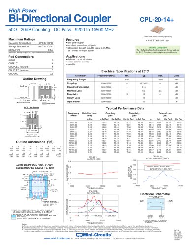 CPL-20-14+
1 Page
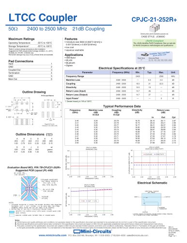 CPJC-21-252R+
1 Page
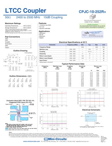 CPJC-10-252R+
1 Page
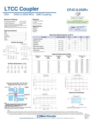 CPJC-6-252R+
1 Page
 BDCN-20-13+
3 Pages
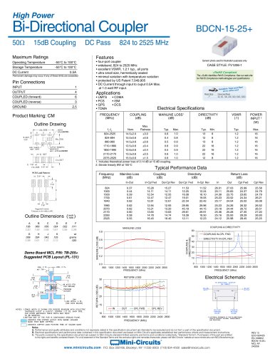 BDCN-15-25+
1 Page
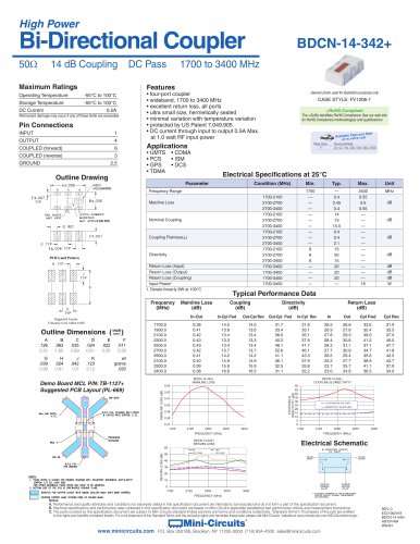 BDCN-14-342+
1 Page
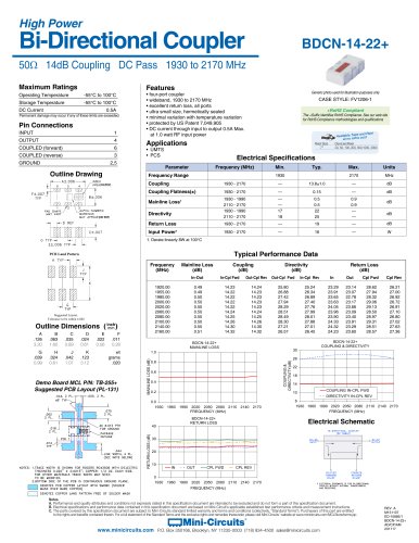 BDCN-14-22+
1 Page
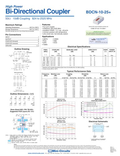 BDCN-10-25+
1 Page
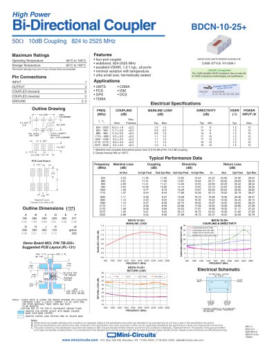 BDCN-10-25+
1 Page
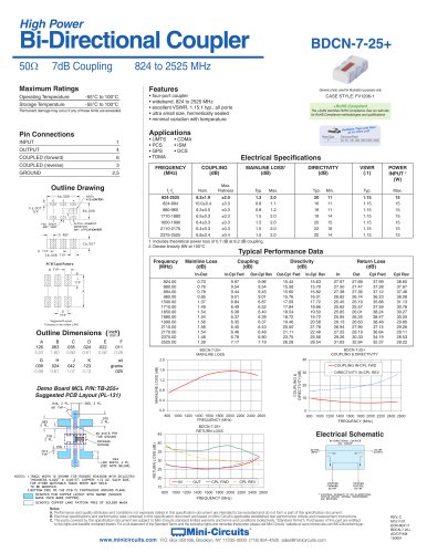 BDCN-7-25+
1 Page
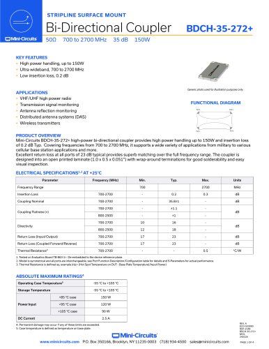 BDCH-35-272+
4 Pages
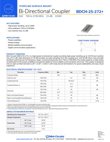 BDCH-25-272+
4 Pages
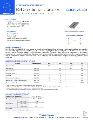 BDCH-25-33+
4 Pages
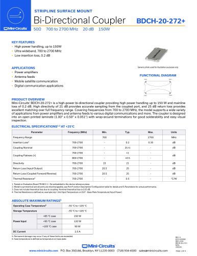 BDCH-20-272+
4 Pages
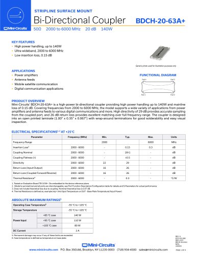 BDCH-20-63A+
4 Pages
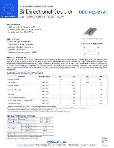 BDCH-15-272+
4 Pages
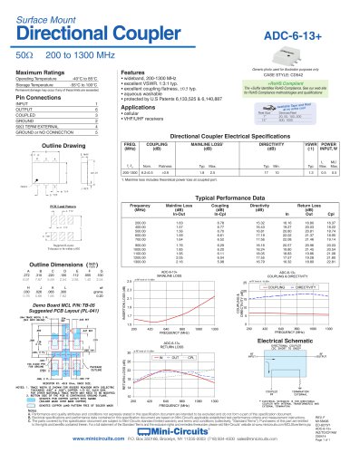 ADC-6-13+ (2025)
1 Page
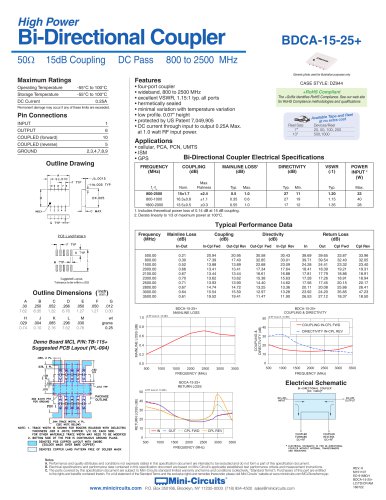 BDCA-15-25+
1 Page
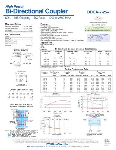 BDCA-7-25+
1 Page
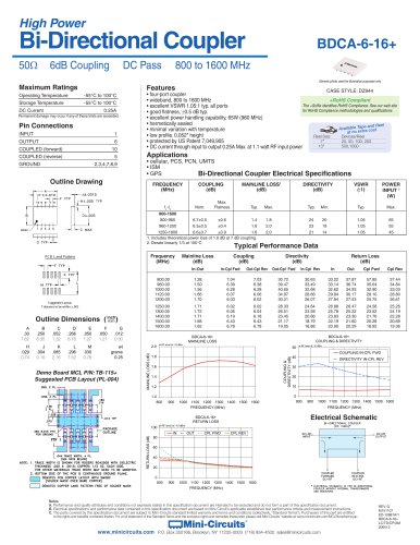 BDCA-6-16+ (2025)
1 Page
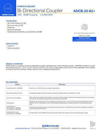 ADCB-20-82+
4 Pages
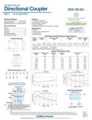 ADC-26-52+
1 Page
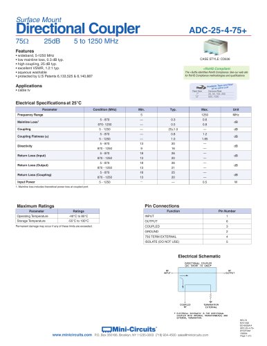 ADC-25-4-75+
2 Pages
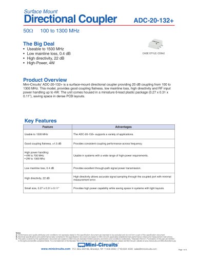 ADC-20-132+
3 Pages
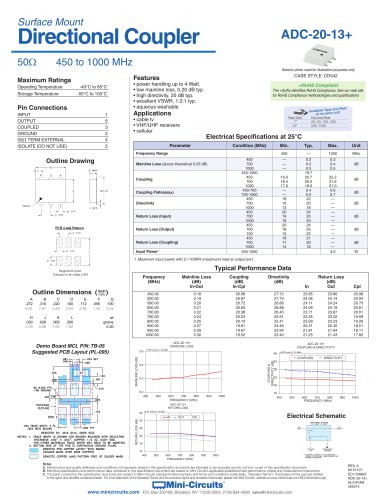 ADC-20-13+
1 Page
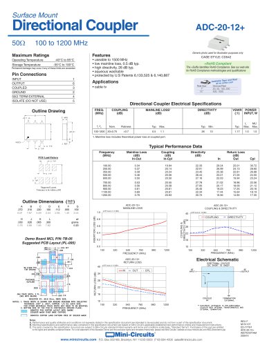 ADC-20-12+
1 Page
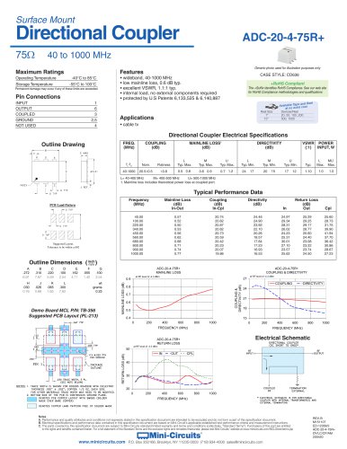 ADC-20-4-75R+
1 Page
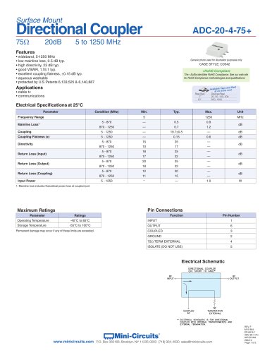 ADC-20-4-75+
2 Pages
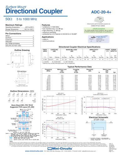 ADC-20-4+
1 Page
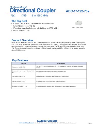 ADC-17-122-75+
3 Pages
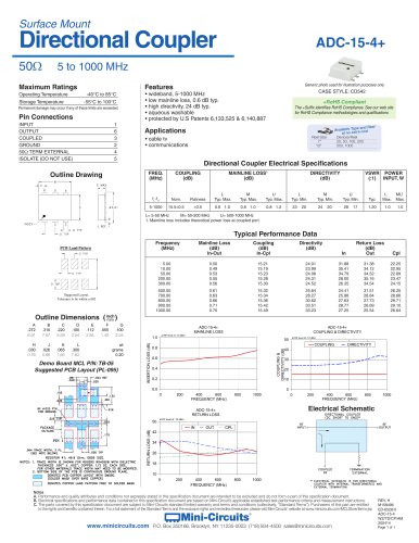 ADC-15-4+
1 Page
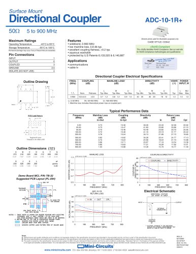 ADC-10-1R+
1 Page
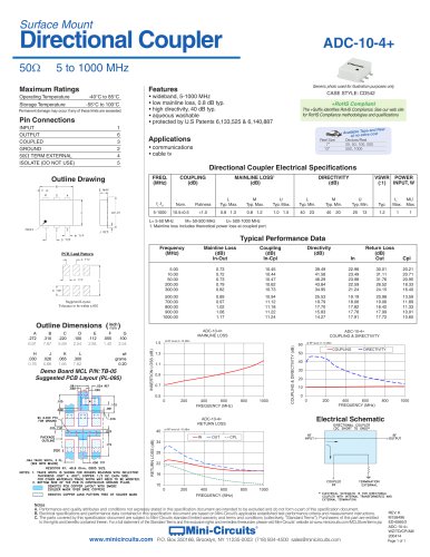 ADC-10-4+
1 Page
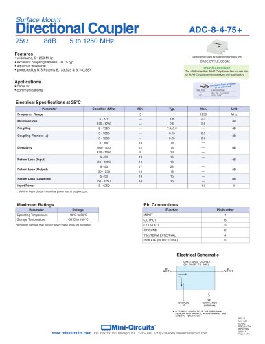 ADC-8-4-75+
2 Pages
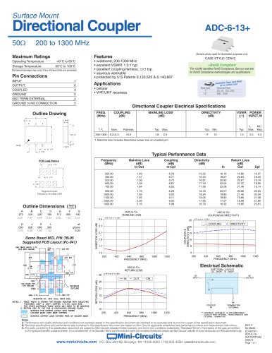 ADC-6-13+
1 Page
 ADC-6-10-75+
1 Page
 BDCA-6-16+
1 Page