- Catalogs
- Miglia Motores
- MOTOR MIG 35 - EN
MOTOR MIG 35 - EN
MOTOR MIG 35 - EN
The MIG 35 motor manual emphasizes the importance of safety due to high voltage and rotating parts. Installation, operation, and maintenance should be conducted by qualified personnel, adhering to safety precautions to prevent injuries. Protective devices should not be ignored or disabled, and proper grounding is essential to avoid serious injury.
Engine Characteristics
The motor is an 'outrunner' type with an external rotor, requiring careful handling when energized. It features a synchronous machine with permanent magnets and radial magnetic flux. Avoid magnetic materials near the motor.
Technical Information
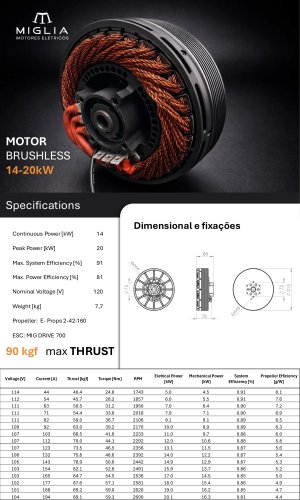
Key specifications include a working voltage of 120V, maximum engine torque of 65 Nm, and maximum current of 200 Arms. The motor has a maximum efficiency of 90% and a continuous power output of 20 kW.
Installation and Maintenance
Installation requires attention to the depth of screws to prevent damage. Power connectors should be covered with heat shrink tubing to prevent short circuits. Maintenance should ensure the motor is disconnected from power and cooled down before proceeding.
Sensors
The motor includes a KTY 84-130 temperature sensor and an optional hall effect sensor, compatible with MIG DRIVE controllers.
Warranty
MIGLIA offers a 12-month warranty against manufacturing defects, with conditions for repair or replacement. The warranty is void if the motor is misused or improperly installed.
Danger and Legal Liability
The manual highlights the risks associated with the motor's lifecycle, including electrical hazards and potential exposure to harmful substances. Compliance with safety and environmental regulations is mandatory to avoid legal consequences.
For further assistance, contact Miglia Electric Motors at [email protected] or call 51 3337 1368.
Catalog excerpts

MIG 35 MOTOR INSTALLATION AND OPERATION MANUAL
Open the catalog to page 1
WARNING: High voltage and rotating parts can cause serious or fatal injury. • Installation, Operation and Maintenance: o It must be performed by qualified personnel. o Observe safety precautions to protect operators from potential injuries. ° Keep installation and maintenance information for future reference. ° Follow all warnings and precautions. • Engine Characteristics: ° "Outrunner" type with external rotor; all visible external parts are ° rotary, including the shaft. o Attention and care are needed when energizing. • Safety Precautions: ° Avoid ignoring or rendering inoperative protective...
Open the catalog to page 2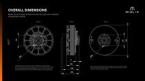
OVERALL DIMENSIONS FIGURE 1: OVERALL DIMENSIONS Below are some basic dimensions that can help when installing the generator engine: Pay attention to the maximum depth of the 6 M8 screws (fig1; detail C) securing the torque transmission flange, which must not exceed 15 mm under any circumstances, otherwise the rotating part may come into contact with fixed parts, potentially causing irreparable damage to the motor/generator. Note 1: Never remove the 8 screws that secure the rotor to the front cover (fig1; detail B). Removing them and their seals will void the motor warranty and may cause irreparable...
Open the catalog to page 3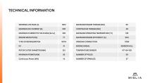
MAXIMUM CURRENT IN THE PHASE [Arms] 350 TYPE OF REFRIGERATION WITH ROTOR OUTER DIAMETER [MM] 215 MAXIMUM ENGINE TORQUE [NM] 65 MAXIMUM OPERATING TEMPERATURE [°C] 130 MAXIMUM ENGINE EFFICIENCY [%] 90% WINDING CONNECTION STAR ENGINE SIGNAL SENSOR HALL
Open the catalog to page 4
INSTALLATION OF POWER CONNECTORS Secure the motor to the mount (image for illustrative purposes only; mount not included) using the 4 screws shown in Figure 2. Use M8 screws (not included), maximum length 60 mm. Note 2: Always cover the power terminals with heat shrink tubing, including screws and nuts, to prevent short circuits and loosening of connections.
Open the catalog to page 5
SENSORS This motor comes equipped with a KTY 84-130 temperature sensor and optional hall effect sensor. To connect it to the MIG DRIVE 1000 or MIG DRIVE 700 controller, simply insert the standard connector into the controller's "hall" plug. The plug is designed so that there is only one way to fit it, therefore no specific position is required.
Open the catalog to page 6
MIGLIA provides a limited warranty for products against manufacturing defects for a period of 12 months from the date of delivery. The established warranty period is independent of the product's installation date and its entry into operation. During the warranty period, MIGLIA may repair or replace, partially or totally, the product that proves to be defective due to unsuitable material or manufacturing and/or assembly defects. The repaired or replaced product will have its warranty extended for a period of 12 months from the date of delivery. In the event of a deviation from the normal operation...
Open the catalog to page 7
DANGER From its supply to its disposal, the equipment safeguarded by this agreement represents risks to the safety and health of individuals who are directly or indirectly involved in its life cycle. Given the constant electrical risk to which individuals in contact with this equipment are exposed, and the risks inherent in contaminants and/or chemicals that may be present in its construction (such as mineral oils, toxic and asphyxiating gases), if it does not meet the standards established in the regulations for accident prevention and current local environmental legislation, its legal maintainer...
Open the catalog to page 8
MIG 35 MOTOR INSTALLATION AND OPERATION MANUAL Porto Alegre/RS - Brazil
Open the catalog to page 10All Miglia Motores catalogs and technical brochures
 Helic
Helic40 Pages
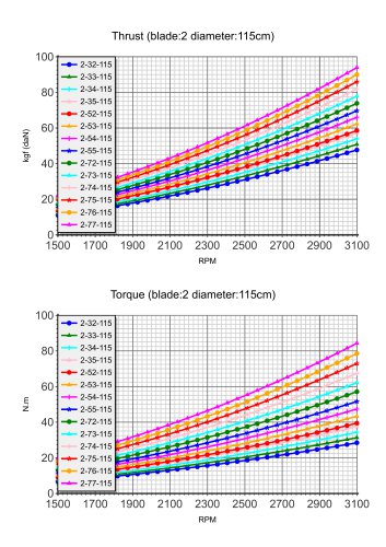
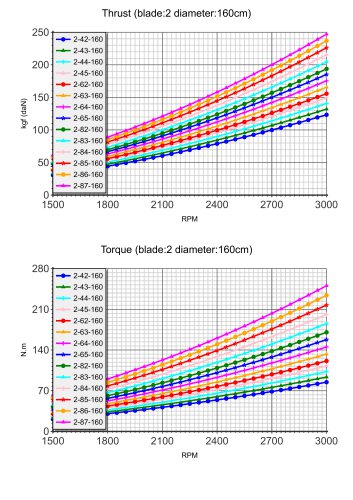 E-Prop 160cm
1 Page
 MIG DRIVE 1000
13 Pages
 MIG DRIVE 700
13 Pages
 MIG35 Miglia
1 Page