Digital transmission in pressure sensors

Digital transmission in pressure sensors
Introduction
The document discusses the design and advantages of digital sensor measuring chains compared to analog ones, particularly in applications requiring high accuracy, such as automotive engine test benches.
Specifications and Design
Digital sensors integrate analog-to-digital conversion and transmit measured values via digital interfaces like CANopen or USB. Analog sensors transmit signals as analog currents or voltages, which are more susceptible to errors.
Advantages of Digital Sensors
- Higher accuracy and resistance to external interference.
- Mathematical compensation of errors in microprocessors, achieving accuracies up to 0.05%.
- Active temperature compensation is possible, eliminating temperature errors.
- Digital signals are immune to interference during transmission, maintaining accuracy over long distances.
Error Influences and Comparisons
Analog measuring chains are prone to errors from environmental influences like temperature and electromagnetic interference (EMC). Digital chains, post-AD conversion, are unaffected by such influences. The document provides a detailed comparison of error influences in analog and digital chains, highlighting the superior accuracy of digital systems.
Cost Considerations
While digital interfaces may have higher initial costs, the overall cost can be lower due to simpler cabling and reduced need for high-cost A/D modules. Digital systems are particularly cost-effective in applications with multiple measuring points.
Conclusion
Digital measuring chains are recommended for applications requiring secure and accurate transmission of measured values, especially in environments with high temperatures and strong EMC interference.
Catalog excerpts
Digital transmission in pressure sensors When accurate values are required in an application, digital sensors are superior to analog instruments. Particularly in automotive engine test benches, accurate pressure measurements are a must. e take a look at the basic design of both analog and digital sensor measuring chains, and also typical error influences. The differences in the wiring and signal evaluation lead to error model calculations that are clearly different from each other. Thus in our example, with lower investment costs, a digital measuring chain can achieve an overall accuracy of 0,1 % while also being more resistant to external interference by design. Whenever accurate measured values are required in an application, the advantages of digital sensors, compared to analog instruments, become obvious. When talking about digital sensors, we mean sensors with an integrated analog-to-digital conversion, which uses a digital interface to transmit the measured value (e.g. CANopen or USB) with the pressure value transmitted as a numeric value. An analog sensor, however, has no built-in analog-to-digital conversion and transmits its signal as an analog current or voltage signal, e.g. 4 V mA to 20 mA, or 0 V to 10 V. Therefore, in applications where high accuracy is required, for example in test stands for propulsion technology, it is advisable to use digital sensors. This avoids further sources of error that exist in analog instruments, over and above the signal conditioning, as a result of the analog signal transmission. Figure 1 shows the schematic design of a typical analog pressure sensor. By the deformation of a diaphragm under a pressure load, a resistance change occurs in the resistance bridge fixed to the diaphragm. This change in resistance is converted into an electrical signal, amplified and transformed into a standard signal. The compensation of the sensor-specific errors (zero error, span error, non-linearity) is also made through analog circuit technology, for example, resistance networks. With digital sensors, however, the electrical signal of the resistance bridge is directly converted into a digital value and the subsequent compensation is instead made mathematically in a microprocessor (see Figure 1). Here, depending on the required accuracy, non-linear errors of any order can be compensated and accuracies up to 0,05 % can be achieved at low costs. By using a μC, an active temperature compensation is also possible, eliminating any temperature error within a defined temperature range. This compensated digital signal now exists in the pressure transmitter as a numerical value and then can be output via any digital protocol (e.g. USB, CANopen, etc.). During the onward transmission of this digital pressure signal, it is now immune to interferences which might cause a further deterioration in the accuracy. If we compare the complete analog measuring chain with its digital counterpart, the advantages of digital sensors become even clearer. Figure 2 shows the schematic structure and at which point external interferences, such as EMC or temperature, introduce additional errors. Initially, the analog front end of both sensor principles is adversely affected by environmental influences such as temperature fluctuations, EMC, etc. However, in the case of the digital pressure transmitter, the pressure signal is no longer influenced by external effects after the AD conversion. In the case of the analog signal chain, even the internal compensation is subject to possible temperature effects due to passive components. The output driver that generates the standardized output signal (e.g. 4 mA to 20 mA or 0 V to 10 V) is also constrained by a variety of external influences (cable length, input impedance of the signal evaluation, temperature, EMC, etc.). Anyone who has tried to evaluate an analog sensor signal with high precision will also know the problem of signal noise. Even in the unpressurized state, the evaluated signal is not fixed at 4 mA but
Open the catalog to page 1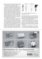
fluctuating within a particular range, e.g. 3985 mA to 4007 mA. This is mainly due to environmental influences which the signal cable picks up, acting as an “antenna”. For further processing, this analog signal value must be digitized, if only for visualization on a display or as a control variable for a controller. I/O channels of programmable logic controllers (PLCs) or external A/D modules can be used for this. These components are also subjected to environmental factors that have a negative impact on the accuracy of the measured value acquisition. Thus, these A/D evaluation modules also have...
Open the catalog to page 2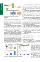
Sensors Figure 2: Analog and digital measuring chains in comparison values by using cyclic redundancy checks (CRC) and for any discrepancies the measured value will be discarded and requested again. To some extent, it is also possible to calculate the correct measured value from the transmitted checksum and thus the transmission errors generated can be corrected. This then avoids re-transmissions and the associated loss of time. In the digital measuring chain design, it is not just the susceptibility to error that is reduced, but also the amount of wiring. Each sensor and actuator no longer needs...
Open the catalog to page 3
Table 1: Comparison of a digital and an analog chain Maurice Bildstein, Stefan Heusel Wika Alexander Wiegand SE & Co. KG www.wika.com for sensors with digital interfaces have decreased in recent years. In the example of the pressure transmitter, one supplier of complete pressure transmitter families lets customers choose between analog and digital output signals at no extra charge. The cables required to transmit digital signals are quite expensive when compared to their analog counterpart, though in the case of a bus system, only one line is required. An analog signal transmission cable is required...
Open the catalog to page 4All Mensor catalogs and technical brochures
 Mensor Sensors
2 Pages
 WIKA Handbook
436 Pages
 Calibration
20 Pages
 Handbook Calibration
73 Pages
 Condensed Custom Systems
4 Pages
 Custom Systems
20 Pages
 Calibration Technology
32 Pages
 Model CPB5000
12 Pages
 Model CPB3800hp
9 Pages
 Model CPB3800
15 Pages
 Model CPB3500
9 Pages
 Model CTP5000
6 Pages
 Models CTP2000, CTP9000
4 Pages
 Model WIKA-Cal
6 Pages
 Model CPA8001
8 Pages
 Model CPC8000-H
7 Pages
 Model CPC8000
8 Pages
 MODEL CPC7000
9 Pages
 Model CPC6050
8 Pages
 Model CPC4000
8 Pages
 Model CPC2000
6 Pages
 Model CPG500
6 Pages
 Model CPG-KITH
6 Pages
 Model CPG-KITP
6 Pages
 Model CPG1500
11 Pages
 CPG2300
2 Pages
 CPG2400 Barometer
2 Pages
 CPA8001
8 Pages
 CPA2501
8 Pages
 CPC8000
8 Pages


- Tester
- Aeronautical tester
- Pressure sensor for the aerospace industry
- Avionics tester
- Aircraft pressure sensor
- Pump
- Aircraft pump
- Absolute pressure sensor
- Pressure tester
- Digital pressure sensor
- OEM pressure sensor
- Booster unit
- Booster unit for the aeronautical industry
- Precision pressure sensor
- Air booster unit
- Air pump
- RS232 pressure sensor
- Nitrogen booster unit