
Catalog excerpts
Design Criteria and Installation and Extraction Procedures for Lee Plug® Expansion Plugs
Open the catalog to page 1
PROCESS SPECIFICATION 203 Revision L2 Design Criteria and Installation and Extraction Procedures for Lee Plug® Expansion Plugs ® Unlimited Distribution The Lee Company Technical Center 2 Pettipaug Road, Westbrook, Connecticut 06498-0424 USA Printed 5/2020
Open the catalog to page 3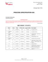
Process Specification 203 Revision L2 March 19, 2020 PROCESS SPECIFICATION 203 Unlimited Distribution: Unlimited distribution. PROPRIETARY NOTICE This document contains confidential, trade secret information which is proprietary to The Lee Company, and is submitted upon the express condition that neither it, nor our products, will be used directly or indirectly in any way detrimental to the interests of The Lee Company, such as disclosure to others or replication of our products, and/or in violation of 18 U.S.C. 1905 (TSA), 5 U.S.C. 552 (FOIA), E.O.12600 of 6/23/87, 18 U.S.C. 1832, and...
Open the catalog to page 4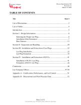
Process Specification 203 Revision L2 March 19, 2020 TABLE OF CONTENTS Title Uncontrolled Copy if Printed; Unless Otherwise Specified
Open the catalog to page 5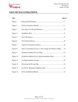
Process Specification 203 Revision L2 March 19, 2020 LIST OF ILLUSTRATIONS Title Uncontrolled Copy if Printed; Unless Otherwise Specified
Open the catalog to page 6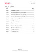
Process Specification 203 Revision L2 March 19, 2020 LIST OF TABLES Title Uncontrolled Copy if Printed; Unless Otherwise Specified
Open the catalog to page 7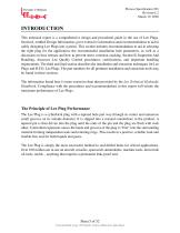
Process Specification 203 Revision L2 March 19, 2020 INTRODUCTION This technical report is a comprehensive design and procedural guide in the use of Lee Plugs. Section I, entitled Design Information, gives extensive information and recommendations to aid in safely designing Lee Plugs into systems. This section includes recommendations to aid in selecting the right plug for the application, the recommended installation hole parameters, as well as a discussion on boss stresses and how to prevent stress corrosion cracking. Section II, Inspection And Handling, discusses Lee Quality Control...
Open the catalog to page 8
Process Specification 203 Revision L2 March 19, 2020 SECTION I - Design Information Selecting the Proper Lee Plug Like Materials The proof pressures listed in the Appendix for all Lee Plugs are for plugs installed in bosses of the same material as the plug. Bosses of considerably higher strengths than the plug may cause low blowout pressures and high pin installation forces. Bosses of considerably lower strengths may also cause low blowout pressures and will make the extractability much more difficult. Proof Pressure To assist designers in the proper selection of Lee Plugs, we give a "proof...
Open the catalog to page 9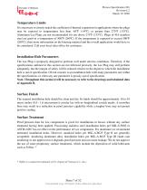
Process Specification 203 Revision L2 March 19, 2020 Temperature Limits It is necessary to closely match the coefficient of thermal expansions in applications where the plugs may be exposed to temperatures less than -65ºF (-54ºC) or greater than 275ºF (135ºC). Aluminum Lee Plugs are not recommended for use above 275ºF (135ºC). Plugs of 416 stainless steel are good to a temperature of 500ºF (260ºC). If the temperature is expected to exceed 500ºF (260ºC), then more information on the housing material and the overall application would have to be considered. Call your local sales office for...
Open the catalog to page 10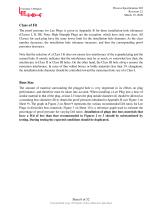
Process Specification 203 Revision L2 March 19, 2020 Class of Fit The proof pressure for Lee Plugs is given in Appendix B for three installation hole tolerances (Classes I, II, III). Note: High Strength Plugs are the exception, which have only one class. All Classes for each plug have the same lower limit for the installation hole diameter. As the class number decreases, the installation hole tolerance increases, and thus the corresponding proof pressures decreases. Note that the selection of a Class I fit does not ensure less interference of the expanded plug and the reamed hole. It merely...
Open the catalog to page 11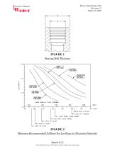
Process Specification 203 Revision L2 March 19, 2020 Housing Wall Thickness Minimum Recommended D/d Ratio For Lee Plugs for Dissimilar Materials Sheet 9 of 52 Uncontrolled Copy if Printed; Unless Otherwise Specified
Open the catalog to page 12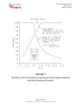
Process Specification 203 Revision L2 March 19, 2020 FIGURE 3 The Effect of D/d on Proof Pressures and Stresses for Plug and Boss Materials with Similar Mechanical Properties. Uncontrolled Copy if Printed; Unless Otherwise Specified
Open the catalog to page 13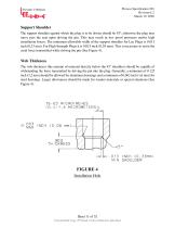
Process Specification Support Shoulder Support Shoulder The support shoulder against which the plug is to be driven should be 45º, otherwise the plug may move past the seat upon driving the pin. This may result in low proof pressures and/or high The support shoulder against which the plug is to be driven should be 45º, otherwise the plug may installation forces. The minimum allowable width of the support shoulder for Lee Plugs is 0.013 move past the seat upon driving the pin. This may result in low proof pressures and/or high inch (0,33 mm). For High Strength Plugs it is 0.015 inch (0,38...
Open the catalog to page 14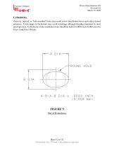
Process Specification 203 Revision L2 March 19, 2020 Cylindricity Oversize, tapered, or "bell-mouthed" holes may result in low installation forces and reduced proof pressures. A hole larger at the bottom may result in leakage although the plug maintains its rated proof pressure. Cylindricity of the installation hole should be held to 0.0003 inch (0,008 mm) for Class I and Class II holes. Uncontrolled Copy if Printed; Unless Otherwise Specified
Open the catalog to page 15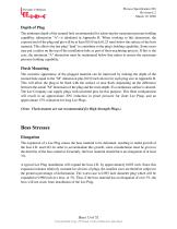
Process Specification 203 Revision L2 March 19, 2020 Depth of Plug The minimum depth of the reamed hole recommended for achieving the maximum pressure holding capability (dimension "A") is tabulated in Appendix B. When working to this dimension, the exposed end of the plug and pin will be at least 0.010 inch (0,25 mm) below the surface of the boss material. This allows the last plug "land" to contribute to the plug's holding capability. Some users may put a radius on the top of the installation hole as part of their machining process. If this is the case, the minimum "A" dimension must be...
Open the catalog to page 16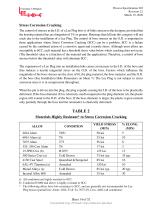
Process Specification 203 Revision L2 March 19, 2020 Stress Corrosion Cracking The control of stresses at the I.D. of a Lee Plug boss is of little concern to the designer, provided that the housing material has an elongation of 3% or greater. Housings that fall into this category will not crack due to the installation of a Lee Plug. The control of boss stresses on the O.D. is important in those applications where Stress Corrosion Cracking (SCC) can be a problem. SCC is a failure caused by the combined action of a corrosive agent and a tensile stress. Although most alloys are susceptible to...
Open the catalog to page 17All The Lee Company catalogs and technical brochures
-
CONTROL SOLENOID VALVES
6 Pages
-
DISPENSE PUMPS
6 Pages
-
AIRCRAFT ENGINE SOLUTIONS
6 Pages
-
LEE TECH TALK
1 Pages
-
SOLENOID VALVES
6 Pages
-
EXTREME ENVIRONMENT CHECK VALVES
94 Pages


