
Catalog excerpts
PROCESS SPECIFICATION 187 Design Criteria and Installation and Extraction Procedures for Lee Hydraulic Inserts
Open the catalog to page 1
PROCESS SPECIFICATION 187 Revision M Design Criteria and Installation and Extraction Procedures for Lee Hydraulic Inserts Unlimited Distribution The Lee Company Technical Center 2 Pettipaug Road, Westbrook, Connecticut 06498-0424 USA Printed 11/2016
Open the catalog to page 2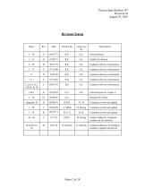
Process Specification 187 Revision M August 29, 2016 Revision Status Initial Release. Update & redrawn. Updated with new information. Updated with new information. Updated with new information. Updated with new information. Updated with new information. Corrected part no. Figure 1. Complete rewrite and update. Complete rewrite and update. Complete rewrite and update Update addresses, telephone numbers & fax numbers Updated addresses & telephone numbers; updated Section III
Open the catalog to page 3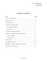
Process Specification 187 Revision M August 29, 2016 TABLE OF CONTENTS Title
Open the catalog to page 4
Process Specification 187 Revision M August 29, 2016 LIST OF ILLUSTRATIONS Sheet FIGURE 1
Open the catalog to page 5
Process Specification 187 Revision M August 29, 2016 LIST OF TABLES Sheet TABLE I
Open the catalog to page 6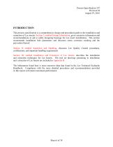
Process Specification 187 Revision M August 29, 2016 INTRODUCTION This process specification is a comprehensive design and procedural guide to the installation and extraction of Lee inserts. Section I, entitled Design Information, gives extensive information and recommendations to aid in safely designing housings for Lee insert installations. This section recommends installation hole parameters and discusses stress corrosion cracking and the prevention thereof. Section II, entitled Inspection and Handling, discusses Lee Quality Control procedures, certifications, and important handling...
Open the catalog to page 7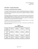
Process Specification 187 Revision M August 29, 2016 SECTION I - Design Information Proof, Burst, and Retention Pressure Ratings Conventional hydrostatic proof and burst pressure testing applies equal pressure to all parts of a Lee restrictor or flow control insert. The Lee insert is therefore unaffected. Maximum hydrostatic pressure in this condition is limited only by the strength of the housing into which the Lee insert is installed. With pressure applied in the flowing direction, conventional hydrostatic proof and burst pressure testing applies equal pressure to all parts of a check...
Open the catalog to page 8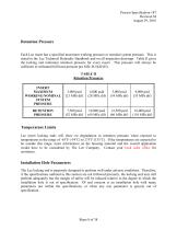
Process Specification 187 Revision M August 29, 2016 Retention Pressure Each Lee insert has a specified maximum working pressure or nominal system pressure. This is stated in the Lee Technical Hydraulic Handbook and on all inspection drawings. Table II gives the locking end minimum retention pressure for every insert. This pressure will always be sufficient to withstand full burst pressure per MIL-H-5440 (H). TABLE II Retention Pressures INSERT MAXIMUM WORKING/NOMINAL SYSTEM PRESSURE RETENTION PRESSURE Temperature Limits Lee insert locking ends will show no degradation in retention pressure...
Open the catalog to page 9
Process Specification 187 Revision M August 29, 2016 Surface Finish The installation hole should be clean and dry. Its finish should be between 16 and 63 microinches RMS (0,4 - 1,6 micrometers) circular lay with no longitudinal scratch marks. A smoother finish may result in a reduction in retention pressure capability while rougher finishes may not permit positive sealing. Surface Treatment Retention pressure data for Lee components is given for installations in holes that have not had special surface treatment. Passivating stainless steel installation holes per ASTM-A-967 or AMS 2700 has...
Open the catalog to page 10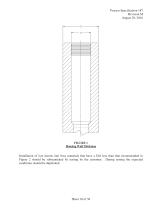
Process Specification 187 Revision M August 29, 2016 FIGURE 1 Housing Wall Thickness Installation of Lee inserts into boss materials that have a D/d less than that recommended in Figure 2 should be substantiated by testing by the customer. During testing the expected conditions should be duplicated.
Open the catalog to page 11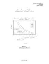
Process Specification 187 Revision M August 29, 2016 Minimum Recommended D/d Ratios for Lee Inserts used with Dissimilar Materials FIGURE 2 FIGURE 2 D/d for Dissimilar Material D/d for Dissimilar Material
Open the catalog to page 12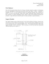
Process Specification 187 Revision M August 29, 2016 Web Thickness The web (the material directly below the 45 degree shoulder) should be capable of withstanding the force transmitted by driving the pin into the insert (See Figure 3 below). Generally, a minimum of 0.125" (3,2 mm) should be allowed for aluminum housings and a minimum of 0.063" (1,6 mm) for steel housings. Many inserts require significantly greater thickness due to their geometry or to protect protruding screens, which is shown on the inspection drawings for all inserts. Larger allowances should be made for weaker materials...
Open the catalog to page 13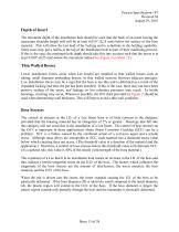
Process Specification 187 Revision M August 29, 2016 Depth of Insert The minimum depth of the installation hole should be such that the back of an insert having the maximum shoulder length will still be at least 0.010" (0,25 mm) below the surface of the boss material. This will allow the last land of the locking end to contribute to the holding capability. Some users may put a radius at the top of the installation hole as part of their machining process. If this is the case, the minimum hole depth should take this into account such that the insert is at least 0.010" (0,25 mm) below the...
Open the catalog to page 14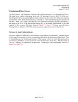
Process Specification 187 Revision M August 29, 2016 Calculation of Boss Stresses The boss stresses, both tangential tensile and the radial compressive, vary throughout the boss. The radial stress reaches a maximum at the hole I.D. and drops to zero at the O.D. of the boss. The tangential stress (assuming a plastic/elastic situation) is low at the I.D. of the boss, reaches its maximum at the plastic/elastic interface, and drops to some intermediate value at the O.D. of the boss. When a Lee insert is installed in a boss material of dissimilar mechanical properties, the stress on the O.D. of...
Open the catalog to page 15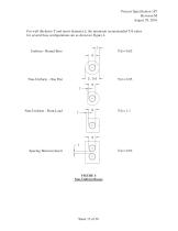
Process Process Specification 187 Specification 187 Process Specification 187 Revision Revision M Revision M M August 29, 2016 2016 August 29,August 29, 2016 ForFor wall thicknessand insert diameter d, thethe minimum recommended T/d ratios wall thickness T T and insert diameter d, minimum recommended T/d ratios for several boss configurations are shown in Figure 4. 4. for several boss configurations are as as shown in Figure Uniform Round Boss Uniform --Round Boss Uniform - Round Boss Non-Uniform - One Flat Non-Uniform One Flat Non-Uniform -- One Flat Non-Uniform Point Load Non-Uniform -...
Open the catalog to page 16All The Lee Company catalogs and technical brochures
-
 CONTROL SOLENOID VALVES
6 Pages
-
 DISPENSE PUMPS
6 Pages
-
 AIRCRAFT ENGINE SOLUTIONS
6 Pages
-
 LEE TECH TALK
1 Pages
-
 SOLENOID VALVES
6 Pages


