- Catalogs
- KOYO BEARINGS VIERZON MAROMME (GROUPE JTEKT)
- Oil Seal & O-Ring
Oil Seal & O-Ring

Oil Seal & O-Ring
- Features: Lightweight, compact, energy-saving, high sealing performance due to optimized lip design, low heat generation, and long service life due to self-lubricating rubber materials.
- Design: Includes various types such as Perfect Seal, Helix Seal, and Super Helix Seal with hydrodynamic ribs for enhanced performance.
- Features: High sealing performance and reliability against various substances, available in diverse designs and sizes, and easy handling.
- Products designed to improve machine performance, reduce weight, size, noise, and vibration. Includes center bearing units, vibration isolating rubber bearings, and more.
- Utilizes Finite Element Method for analyzing non-linear materials like rubber, aiding in the development of new products and enhancing research and product development.
- Oil Seals: Covers nomenclature, functions, selection, design, characteristics, handling, and failure countermeasures.
- O-Rings: Discusses classification, numbering systems, selection, technical principles, groove design, handling, and failure countermeasures.
- Includes applications in automobiles, motorcycles, rolling mills, geared motors, and hydraulic motors.
- Provides engineering data such as rubber-material properties, conversion factors, and tolerance tables.
- Includes forms for oil seal design and production requests.
- Material: Steel or cast iron is preferred for housings. Aluminum or plastic requires careful consideration due to different linear expansion coefficients, which can lead to seal dislocation or leakage.
- Dimensional Accuracy: Housing bore tolerance should be H7 or H8 for bores up to 400 mm, and H7 for larger bores.
- Chamfer: Chamfers should be provided at the housing bore inlet to facilitate seal mounting and prevent damage.
- Housing Shoulder Diameter: Specific dimensional requirements must be met if the housing bore has a shoulder.
- Surface Roughness: Bore surface should be finished to specified roughness to ensure proper seal seating and prevent leakage.
- Total eccentricity, the sum of shaft runout and housing-bore eccentricity, affects sealing performance. It is expressed in TIR (Total Indicator Reading).
- Allowable total eccentricity depends on seal characteristics, shaft diameter tolerance, temperature, and rotational speed.
- Sealing Property: Oil seals prevent fluid leakage by creating a pumping effect through the main lip shape and contact with the rotating shaft.
- Seal Service Life: Influenced by factors like temperature, eccentricity, rotational speed, and lubrication. Service life estimation is based on rubber material, lubricant, and lip temperature.
- Lip Temperature: Estimation involves calculating peripheral speed and considering ambient temperature.
- Allowable Peripheral Speed: Influenced by shaft runout and rubber material. It determines the speed at which sealing performance deteriorates.
- Allowable Internal Pressure: Dependent on shaft runout and housing-bore eccentricity.
- Seal Torque: Determined by lip radial load, coefficient of friction, and shaft diameter. Initial torque may be high but stabilizes over time.
- Storage: Proper storage conditions are crucial to prevent oil leakage. Store seals in air-conditioned environments with temperatures not exceeding 30°C and humidity between 40% and 70%. Use older seals first and avoid direct sunlight, ozone, and mechanical damage. Seals should not be stacked or hung to prevent deformation.
- Mounting: Before mounting, ensure seals are clean and undamaged. Apply suitable lubricant to the seal lip. Use lithium-based grease for lubrication, avoiding silicone or urea-based greases for specific rubber types. In cold areas, warm the seal before mounting. Ensure the shaft edge is chamfered to prevent damage during installation.
- Handling: Avoid excessive impact and use kerosene for cleaning. Do not use corrosive fluids or hang seals by wires, which can cause deformation.
- Press-Fitting: Use appropriate jigs for press-fitting seals into housing bores. Ensure seals are mounted at right angles to prevent leakage. Refer to diagrams for required pressing loads based on seal dimensions.
- Seal Failures and Countermeasures: Common causes of seal failures include improper handling, excessive pressure, and poor lubrication. Countermeasures involve correcting shaft chamfers, improving lubrication, and using high-pressure proof seals. Tables provide detailed causes and solutions for various seal failure symptoms.
- Oil seals are categorized by type, including standard and special seals, with dimensions ranging from d1 6 to d1 3,530.
- Rubber materials used include nitrile, acrylic, silicone, and fluoro rubber, each with specific applications and limitations.
- Seal numbers are constructed using type codes and dimensional numbers, indicating bore diameter, outside diameter, and width.
- Lip Deformation: Caused by rubber hardening and oil temperature rise. Countermeasures include using high-temperature proof rubber and examining temperature increase causes.
- Lip Face Contact: Issues like excessive inside pressure and shaft runout require structural changes, clearance adjustments, and shaft accuracy improvements.
- Blistering: Due to high-temperature oil agglomeration, requiring improved lubrication and shaft surface finish corrections.
- Oil Leakage: Often results from improper seal dimensions, surface finish, or mounting direction. Solutions include correcting bore diameter, replacing seals, and improving surface finishes.
- Detailed tables list symptoms, phenomena, causes, and countermeasures for various seal failures, emphasizing the importance of correct dimensions, material selection, and installation techniques.
- Common causes include improper housing bore dimensions, poor lubrication, and incorrect seal mounting.
- Countermeasures focus on improving material properties, adjusting dimensions, and refining installation processes.
- Tables provide boundary dimensions for different seal types, indicating the range of sizes available for various applications.
- Specific dimensions are provided for metal and rubber O.D wall seals, with notes on production capabilities and inventory considerations.
- Material Resistance: The document outlines the resistance of various O-ring materials to different substances, including mineral oils, gasoline, animal and vegetable oils, and brake fluids. It categorizes materials based on their resistance to high temperatures and other conditions.
- Material Classes: O-rings are classified into different classes such as JIS NBR-70-1, NBR-90, and FKM-70, each with specific applications and resistance properties.
- Applications: O-rings are used for dynamic use, static sealing, vacuum flanges, and slim static sealing. The document specifies which materials are suitable for each application.
- Purpose: Backup rings are used with O-rings to prevent extrusion from the groove, especially under high pressure.
- Types and Materials: Backup rings come in spiral, bias-cut, and endless designs, made from tetrafluoroethylene resin, which is chemically stable and corrosion-resistant.
- Applications: Different designs are recommended based on pressure and temperature conditions, with specific guidelines for installation.
- Designation Numbers: O-ring and backup ring designation numbers consist of material, application, and dimensional codes, providing a standardized way to identify and select the appropriate O-ring.
- Material Selection: The document provides guidance on selecting O-ring materials based on chemical stability with the substances they will contact.
- Cross Section Diameter: Recommendations are given for the compression rate of O-rings to ensure effective sealing without permanent deformation.
- Deformation Under Pressure: O-rings provide a self-seal through elasticity at low pressure and better sealing at higher pressure. Backup rings are recommended for high-pressure applications to prevent extrusion.
- Backup Ring Installation: Guidelines for installing backup rings to extend O-ring service life and prevent damage are provided.
- Sealing Mechanism: O-rings are used for sealing under various pressure conditions. Proper installation is crucial to prevent slack, especially for large O-rings. For sizes 150 mm or more, a slightly smaller O-ring may be used to ensure proper compression.
- Static Sealing: For cylindrical surfaces, groove accuracy is critical. For flat surfaces, the O-ring compression should be slightly larger. In vacuum applications, careful machining and material selection are necessary.
- Installation in Triangular Grooves: The groove dimension should be 1.3 to 1.4 times the O-ring cross-section diameter.
- Compression Amount and Rate: The compression rate should be between 8% and 30%. The groove width should ensure the O-ring occupies no more than 90% of the space.
- Extrusion and Surface Roughness: The gap and pressure influence extrusion. Surface roughness should meet specified standards to ensure sealing performance.
- Material and Surface Finishing: Steel is recommended for dynamic sealing applications. Surface finishing methods include honing and hard-nickel plating for durability.
- Storage: Store O-rings away from sunlight, heat, and ozone. Maintain a temperature below 30°C and humidity below 65%.
- Handling: Avoid reusing O-rings. Apply lubricant during installation and avoid twisting. Protect O-rings from sharp edges and cleaning oils.
- Common Issues: Twisting, chipping, permanent set, abrasion, hardening, swelling, scratching, protrusion, tearing, and ozone cracking.
- Solutions: Improve installation techniques, use appropriate materials, and ensure proper groove dimensions and surface finishes.
- Materials: The O-rings are made from various materials including JIS NBR-70-1, NBR-90, EPDM-70, EPDM-90, VMQ-70, FKM-70, FKM-90, HNBR-70, HNBR-90, ACM-70, and SBR-70. These materials are not standardized in the JIS.
- Dimensional Tolerances: The tolerance for bore diameter d1 is specified in JIS B 2401 for certain materials, with variations for others like VMQ-70 and ACM-70 (1.5 times the standard) and FKM-70, FKM-90, HNBR-70, and HNBR-90 (1.2 times the standard).
- Static Sealing: For static sealing on flat surfaces, grooves should be designed according to dimension d8 for external pressure and d7 for internal pressure. This ensures the O-ring maintains close contact with the groove walls.
- Dynamic Sealing: Backup rings are recommended for dynamic sealing and static sealing on cylindrical surfaces to enhance performance.
- Eccentricity: Defined as the difference between the maximum and minimum values of dimension K, or double the coaxiality measurement.
- The document includes extensive tables listing O-ring numbers, groove dimensions for both static and dynamic sealing, and corresponding fitting codes. These tables provide precise measurements for bore diameter, cross-section diameter, and groove dimensions.
- Design considerations for O-rings under different pressure conditions are emphasized to ensure optimal sealing performance.
- Backup rings are suggested for certain applications to prevent extrusion and improve sealing efficiency.
- O-ring Dimensions: The document lists various O-ring numbers with corresponding groove dimensions for static sealing on flat and cylindrical surfaces. It specifies bore diameter (d1), cross-section diameter (d2), and groove dimensions (d3, d5, d8 for external pressure and d4, d6, d7 for internal pressure).
- Material Specifications: O-rings are made from materials such as JIS NBR-70-1 and FKM-70, with specific tolerances for each material type.
- Design Guidelines: For static sealing on flat surfaces, grooves should be designed according to dimension d8 for external pressure and d7 for internal pressure. This ensures proper contact between the O-ring and the groove walls.
- Compression Rate: The groove depth (K) should be determined to achieve an O-ring compression rate between 8% and 30%.
- Fitting Codes: The fitting codes correspond to the tolerances of d4 and d6 dimensions, ensuring proper fit and function of the O-rings.
- Old ISO 3601: The document references the old ISO 3601 standard for general industrial applications, specifying dimensions and tolerances for O-rings.
- Backup Rings: For dynamic sealing and static sealing on cylindrical surfaces, the use of backup rings is recommended to enhance sealing performance.
- Eccentricity Measurement: Eccentricity (E) is defined as the difference between the maximum and minimum values of dimension K, or double the coaxiality measurement, which should be minimized for optimal sealing.
- The tables provide detailed dimensions for various O-ring sizes, including bore diameter, cross-section diameter, and groove dimensions for both static and dynamic sealing applications.
- Specific tolerances are provided for each dimension to ensure proper fit and sealing performance.
- O-ring Dimensions: The document lists various O-ring sizes with specific cross-section diameters (d2) and bore diameters (d1), along with tolerances. Materials include JIS NBR-70-1, NBR-90, and FKM-70.
- Backup Ring Dimensions: Backup rings are specified with dimensions for spiral, bias-cut, and endless rings, made from tetrafluoroethylene resin. The document provides detailed measurements for each type.
- O-ring Installation: Guidelines are provided for determining groove depth (K) and width (b) to ensure proper compression rates and occupancy percentages. The radial gap should be minimized as per specified values.
- Backup Ring Installation: Instructions include maintaining specific cut angles and thickness deviations for bias-cut and endless rings.
- The document references JIS B 2401 standards for bore diameter tolerances and material specifications.
- It also mentions specific tolerances for different materials, such as VMQ-70 and ACM-70, which have different tolerance multipliers.
- For FKM-70 products, consultation with JTEKT is advised for specific tolerance values.
- Ensure that O-rings do not occupy more than 90% of the groove space to maintain functionality.
- Automobile: Includes applications in automatic and manual transaxles, engines, and electric power steering systems.
- Motorcycle: Focuses on engine applications.
- Rolling Mill and Stock Axles: Discusses the use of rolling bearings and oil-film bearings.
- Hydraulic and Geared Motors: Provides examples of seal applications in these systems.
- Motorcycle Engines: Utilizes rubber-covered seals with minor lips for effective sealing.
- Rolling Mill Roll Necks: Employs scale seals, water seals, and large-size oil seals for oil-film bearings and rolling bearings.
- Rolling Stock Axles: Features metal ring integral seals with reinforcement rings for double row cylindrical and tapered roller bearings.
- Hydraulic Motors: Uses pressure-resistant seals and rubber-covered seals without springs.
- Geared Motors: Incorporates rubber-covered seals with minor lips and sludge lip integral rubber-covered seals.
- Rubber Material Varieties: The document compares properties of various rubber materials, including Nitrile Rubber (NBR), Hydrogenated Nitrile Rubber (HNBR), Acrylic Rubber (ACM and ANM), Silicone Rubber (VMQ), and Fluoro Rubber (FKM).
- Properties: Each material is evaluated based on specific gravity, Mooney viscosity, hardness, tensile strength, elongation, temperature range, and resistance to various chemicals and environmental conditions.
- SI Units and Conversion Factors: Provides conversion tables for various units of measurement, including length, area, volume, mass, force, pressure, and more.
- Shaft and Housing Tolerances: Details the deviation classes for shaft diameters and housing bore tolerances, ensuring precise fitting and performance.
- This section outlines the nominal shaft and bore diameters, along with their respective tolerance classes. It includes detailed tables specifying the permissible deviations for various diameter ranges, ensuring precision in manufacturing and assembly processes.
- The document provides guidelines for calculating temperature conversions between Celsius and Fahrenheit, as well as viscosity conversions using different scales such as Saybolt, Redwood, and Engler. These procedures are crucial for ensuring accurate measurements in engineering applications.
- Standards for steel hardness conversion are detailed, including Rockwell, Vicker's, and Brinell scales. This ensures consistency in material properties across different measurement systems.
- Recommendations for shaft surface speed and rotational speed are provided, along with a quick reference diagram. This aids in selecting appropriate speeds for different shaft diameters to optimize performance and longevity.
- The document includes request forms for oil seal design and production, which require detailed information about the application, including dimensions, motion type, and environmental conditions. This ensures that the correct oil seal is selected for specific applications.
- Tables provide critical data on permissible deviations for shaft and bore diameters, temperature conversion values, viscosity measurements, and steel hardness scales. These are essential for ensuring compliance with engineering standards and optimizing component performance.
- Mounting Direction: The oil seal can be mounted in X/Y direction into housing and A/B direction onto the shaft. The shaft can rotate in Right, Left, or Bi-direction.
- Rotational Direction: Clockwise when viewed from the air side face of the oil seal and counterclockwise from the same perspective.
- Direction: Right and Left options are available.
- Internal/External: Options for internal and external mounting are provided.
- Shaft Diameter: Changeable with specified maximum and minimum values.
- Oil Seal Type: Specify if the requested type is available.
- Housing Bore Diameter: Changeable with specified maximum and minimum values.
- Rubber Material: Specify if the requested type is available.
- Width: Changeable with specified maximum and minimum values.
- Oil Seal Life: Specify the requested lifespan.
- Mounting Location Details: Attach a drawing if possible.
Catalog excerpts
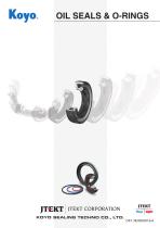
OIL SEALS & O-RINGS OIL SEALS & O-RINGS
Open the catalog to page 1
OIL SEALS fi O-RINGS ■ Koyo Oil Seals: Features ■ Koyo O-Rings: Features ■ Koyo Functional Products: Features ■ FEM (Finite Element Method) Analysis 1. Oil Seals Engineering Section Dimensional Tables 2. O-Rings Engineering Section Dimensional Tables Engineering Data 5. Request Forms for Oil Seal Design and Production
Open the catalog to page 2
JTEKT CORPORATION KOYO SEALING TECHNO CO., LTD.
Open the catalog to page 3
Preface This catalog lists Koyo oil seals and O-rings, including all items of the dimension series specified in ISO, JIS and JASO (Japanese Automobile Standards Organization) standards. This catalog is also based on knowledge gained from our supply record, experience, expertise, technologies, and research developments that JTEKT and KOYO SEALING TECHNO have acquired in cooperation with customers since its foundation in 1964. A specialty of this new catalog is the comprehensive information, it offers regarding the selection and handling of oil seals and O-rings. Energy-saving, efforts to protect...
Open the catalog to page 4
3. Application Examples of Oil Seals and O-Rings 3.1 3.2 3.3 3.4 3.5 3.6 5. Request Forms for Oil Seal Design and Production
Open the catalog to page 5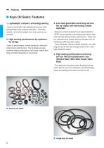
■ Koyo Oil Seals: Features 1. Lightweight, compact, and energy-saving Koyo oil seals offer high sealing performance, while being compact with reduced seal width. They help reduction of machine weight, size, and resource consumption 2. High sealing performance by optimum lip design Koyo oil seals employ a linear-contact lip, which provides proper radial lip load. The lip design ensures excellent sealing performance, low torque, proper flexibility and high allowability for eccentricity. 3. Low heat generation and long service life by highly self-lubricating rubber materials Based on extensive research...
Open the catalog to page 6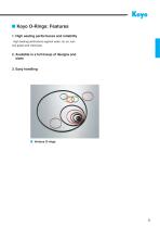
■ Koyo O-Rings: Features 1. High sealing performance and reliability High sealing performance against water, oil, air, various gases and chemicals. 2. Available in a full lineup of designs and sizes 3. Easy handling
Open the catalog to page 7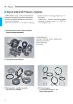
■ Koyo Functional Products: Features JTEKT produces various functional products based on advanced sealing technologies and sophisticated manufacturing expertise acquired through extensive research and development. Koyo functional products are very helpful in improving machine performance, reducing weight, size, noise and vibration. Consult JTEKT if there is no product in this catalog that exactly matches your requirements--JTEKT can custom-design products. 1. Functional products for automobiles and industrial machinery • Center bearing unit • Bearings molded with vibration isolating rubber •...
Open the catalog to page 8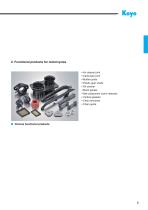
2. Functional products for motorcycles • Air cleaner joint • Carburetor joint • Muffler joints • Plastic gear shafts • Oil strainer • Mesh gasket • Ball-component clutch releases • Vertical gaskets • Chain tensioner • Chain guide
Open the catalog to page 9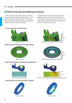
■ FEM (Finite Element Method) Analysis JTEKT uses the non-linear finite element method to analyze non-linear materials such as rubber, for which accurate analysis was difficult before. The company has been studying sealing-mechanism theories by this method in order to develop new products. The findings so far have been very useful for basic research as well as for rubber-component design. The FEM is our common design tool today, enabling highly reliable analysis and evaluation, speeding up research and product development. Pressure deflection, stress analysis Stress High Tension Low Under load...
Open the catalog to page 10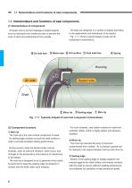
1.1 Nomenclature and functions of seal components 1.1 Nomenclature and functions of seal components (1) Nomenclature of components Oil seals are designed in a variety of shapes according to the applications and substances to be sealed. Fig. 1.1.1 shows a typical shape of seal and its component nomenclature. Oil seals work to prevent leakage of sealed objects such as lubricants from inside and also to prevent the entry of dust and contaminants from outside. 5 Metal case 6 O.D surface 7 Fluid side face Sealed side Fig. 1.1.1 Typically shaped oil seal and component nomenclature (2) Component functions...
Open the catalog to page 12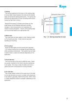
Because this spring is a closely wound type coil, the initial tension can be obtained high level, and then changes in load characteristics can be gradual with respect to spring elongation. Tension at the sealing edge can thus be kept stable at an appropriate level. Spring rate (slope of line) Spring load The spring supplements the tension at the sealing edge to ensure tight contact between the shaft and the sealing edge and enhanced sealing performance. The spring also prevents the deterioration of main lip sealing performance caused by high heat or others. Inflection point Initial tension Service...
Open the catalog to page 13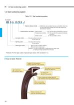
1.2 Seal numbering system 1.2 Seal numbering system Table 1.2.1 Seal numbering system MH: O.D wall is rubber material HM: O.D wall is metal case HM(S)H: O.D wall is metal with a reinforcing inner metal case. (A spring is always provided for this type.) Remark) For the type codes of special type seals, refer to Section 1.3. ■ Koyo oil seals: Features Rubber O.D wall prevents leakage efficiently under pressure Nose gasket prevents leakage through the seal O.D Light metal case with sufficient rigidity Lip design with excellent followability Linear contact type sealing edge with high durability under...
Open the catalog to page 14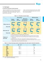
Table 1.3.2 lists the seal type codes used at JTEKT, along with the corresponding codes used in the ISO, JIS, and JASO standards. 1.3 Seal types (1) Common seal types and their features Seals are classified by O.D wall material, lip type and whether with spring or without spring. Major oil seals are specified in ISO 6194 and JIS B 2402. Table 1.3.1 shows common seal types. Table 1.3.1 Oil seals of common types With spring Without spring Metal O.D wall with a reinforcing ^3) 4) inner metal case Rubber O.D wall Without minor lip Type code MHS Type code Features of each type 1) With spring type...
Open the catalog to page 15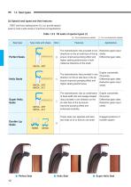
1.3 Seal types (2) Special seal types and their features JTEKT and Koyo sealing techno Co.,Ltd. provide special seals to meet a wide variety of machines and applications: Table 1.3.3 Oil seals of special types (1) : For bi-directional rotation Seal type Type code and shape Perfect Seals The hydrodynamic ribs provided in two Reduction gears input directions on the air side face of the lip shafts ensure improved pumping effect and Differential gear sides higher sealing performance in both rotational directions of the shaft. Helix Seals MHSA...XRT MHSA...XLT MHSA...XRT MHSA...XLT Double Lip Seals...
Open the catalog to page 16All KOYO BEARINGS VIERZON MAROMME (GROUPE JTEKT) catalogs and technical brochures
 Standard Bearings
241 Pages
 Ball & Roller Bearing
84 Pages
 TAPERED ROLLER BEARINGS
107 Pages
 Needle Roller Bearings
274 Pages
 LARGE SIZE BALL & ROLLER BEARINGS
247 Pages
Archived catalogs
 B1005E EXSEV Product Guidebook
13 Pages
 B1013E Ceramic Bearings
17 Pages
 B1011E Traction Drive Unit
4 Pages
 B2004E Ceramic & EXSEV
71 Pages
 B1021E Slim Bearing
2 Pages
 High Wing Series Drive Shafts
30 Pages
 Wind Turbine Generators
4 Pages
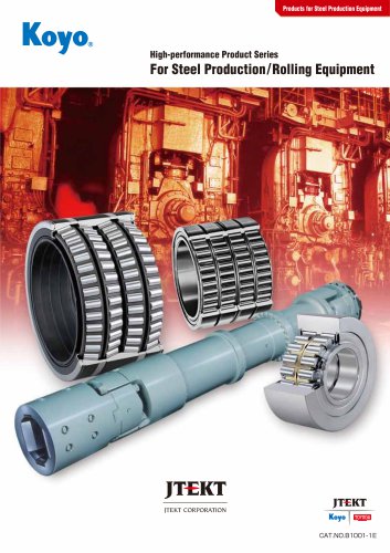
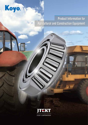
 Agriculture and Construction
6 Pages


- Ball bearing bearing
- Steel bearing
- Airliner bearing
- Precision bearing
- Radial bearing
- Single-row bearing
- Double-row bearing
- Heavy-duty bearing
- Pre-lubricated bearing
- Deep groove bearing
- Cylindrical roller bearing
- Axial bearing
- Self-aligning bearing
- Bearing with cage
- High-speed bearing
- Sealed bearing
- Stainless steel bearing
- Tapered roller bearing