- Catalogs
- KOYO BEARINGS VIERZON MAROMME (GROUPE JTEKT)
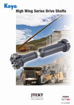
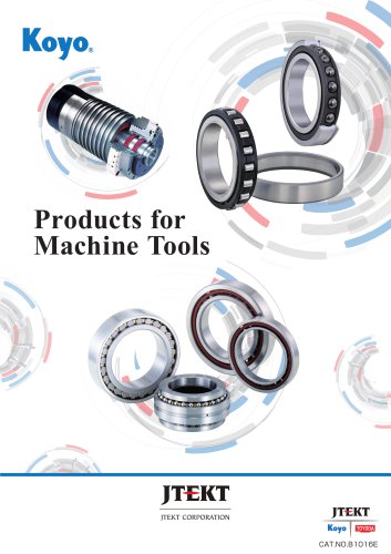
- High Wing Series Drive Shafts
High Wing Series Drive Shafts

High Wing Series Drive Shafts
Drive shafts are essential for transmitting rotational torque between non-aligned shafts. They include universal joints with cross & bearings to reduce torque loss and provide flexibility. Key components are cross & bearings, spline sleeves, and bearing set bolts.
Efforts to Improve Reliability
JTEKT has improved drive shaft reliability by extending greasing intervals, enhancing abrasion resistance, and optimizing oil seals. The spline seal structure now includes a urethane rubber seal and double cover for better durability against muddy water.
Handling Guidelines
Proper handling involves avoiding hard impacts, using specified bolts and torque wrenches, and following recommended greasing intervals with lithium grease. Disassembly of cross & bearings should be avoided unless necessary.
Failure Cases and Measures
Common failures include flaking, breakage, and bolt fatigue. Solutions involve checking usage conditions, ensuring proper torque, and possibly increasing component size.
Technical Data
Universal joints show angular velocity and torque fluctuations. Proper installation requires aligning yokes and maintaining equal operating angles. Secondary couples, which add loads, must be considered in design.
Drive Shaft Selection
Selection criteria include load torque, mean torque, and service life. Maximum and mean torque values help determine the appropriate drive shaft size, with safety factors for normal and emergency conditions. JTEKT provides empirical equations for estimating service life.
Specifications and Analysis
The document details specifications for various drive shafts, including telescoping and fixed types. Key parameters include metric screw thread size M14×1.5, tightening torque of 206 to 220 N・m, and specific dimensions for length and allowable telescoping stroke.
Procedures and Evaluation
JTEKT uses advanced analysis techniques like FEM with 3D models to optimize design and ensure product suitability. The document emphasizes reviewing allowable differential angles based on market experience.
Drive Shaft Selection
A selection sheet helps choose the appropriate drive shaft based on torque transmission, rotational speed, operating angle, and environmental conditions. Service life and attaching dimensions are also considered.
Contact Information
Contact details for JTEKT and KOYO offices worldwide are provided, including locations in Canada, Mexico, Brazil, the Middle East, India, Thailand, Indonesia, Singapore, North America, the Philippines, Korea, China, Australia, Europe, and Japan.
Notes
While efforts are made to ensure data accuracy, JTEKT cannot assume responsibility for errors or omissions. Reproduction of the catalog without written consent is prohibited.
Catalog excerpts
High Wing Series Drive Shafts High Wing Series Drive Shafts
Open the catalog to page 1
High wing series drive shafts that handle all kinds of environment with proven results, technology, research and dev elopment CONTENTS ■ Introduction to drive shaft In order to improve the reliability of our drive shafts under severe conditions, JTEKT has been continuously committed to research and development of technologies, built upon a wealth of results and experiences achieved with our customers over many years. Our products also have high compatibility through adoption of standard mounting dimensions. This catalogue includes dimension tables for respective model numbers, technical data,...
Open the catalog to page 2
Our drive shafts for construction machinery and railway rolling stocks to meet your needs Introduction to drive shafts Functions A drive shaft is a device to smoothly transmit rotation torque by connecting a driving shaft and a driven shaft that are not aligned on the same axis. Since it has two universal joints on one shaft, it can connect the driving shaft and the driven shaft flexibly. In addition, one universal joint has four rolling bearings (cross & bearing) that can minimize torque loss with low friction. Appearance and configuration of drive shafts 【The appearance and component configuration...
Open the catalog to page 3
Efforts to improve reliability 1. Long-interval greasing cross & bearing Features (1) Oil seal lip from double to triple, and the optimization of shape and position. (2) Reduction of roller contact stress with torque load by length up and crowning optimization (3) Abrasion resistance improved by adding glass fiber to thrust washer (4) Bearing cup shape reviewed and cost reduced by abolishing the roller washer Cross & bearing structure Thrust washer (POM) Roller washer Roller Abrasion resistance improved by adding glass ber Reduction of contact stress by length up and crowning optimization Oil...
Open the catalog to page 4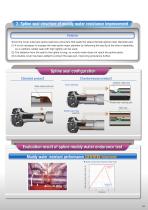
2. Spline seal structure of muddy water resistance improvement Features Since the cover tube type spline seal has a structure that seals the sleeve (female spline) outer diameter part, (1) It is not necessary to surpass the male spline major diameter by deforming the seal lip at the time of assembly, so a urethane rubber seal with high rigidity can be used. (2) The distance from the seal to the spline is long, so muddy water does not reach the spline easily. (3) A double cover has been added to protect the seal part, improving endurance further. Spline seal con guration 【Standard product】 【Countermeasure...
Open the catalog to page 5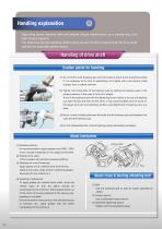
Handling explanation High wing series features safe and secure torque transmission by a parallel key, and high torque capacity. The following are the handling method and caution points to ensure that the drive shaft delivers its expected performance. Handling of drive shaft Caution points for handling (1) Do not hit the cross & bearing part with hard metal so that a shock should be avoided. If it is necessary at the time of assembling, hit it lightly with a non-ferrous metal (copper, etc.) or plastic hammer. (2) Tighten the fixing bolts of the bearing cups by setting the bearing cups in the proper...
Open the catalog to page 6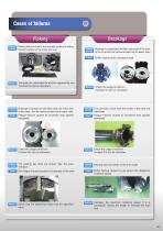
Breakage Failures example Failures example Flaking has occurred in the raceway surface of rolling contact surface of the cross and cup. Compare the calculated life and the required life and increase the size as necessary Breakage is caused from the fillet radius part of the neck of the cross and the fracture surface has no beach mark Check the usage conditions Increase the size as necessary The tube has a crack near the border of the tube and weld bead Fatigue fracture caused by excessive load applied repeatedly Failures example Check that the tightening torque has the specified value Bending...
Open the catalog to page 7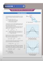
Technical data 1 General characteristics of universal joint Single universal joints Driven shaft Shaft operating angleθ The driving shaft and driven shaft intermediated by a universal joint has the following relationship between their rotational angles: where Rotational angle of driving shaft : : Rotational angle of driven shaft : Shaft operating angle (Fig. 1) Fig. 1 Single universal joint This means that, even if the rotational speed and torque of the driving shaft are constant, the driven shaft is subject to fluctuation in rotational speed and torque. The speed ratio between the...
Open the catalog to page 8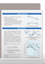
Double universal joints Universal joints are usually installed in pairs. When assembled as shown in Fig. 4, that is, (1) With equal operating angles in both joints (2) Yokes connected to the same shaft in line (3) Central lines of all three shafts (driving shaft, intermediate shaft, and driven shaft) in the same plane, the driven shaft rotates exactly in the same way as the driving shaft. Therefore, they should be attached as shown in the figure on the right as far as possible. Secondary couple It is often necessary to consider the secondary couples imposed by universal joints operating at an...
Open the catalog to page 9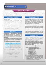
Drive shaft selection A drive shaft should be selected so as to satisfy the required strength, service life, operating angle and dimensions necessitated by its purpose. Especially, a drive shaft can be selected if it meets conditions of both strength and life of the universal joint, except for special cases. To decide the size of the drive shaft, it is necessary to grasp the load torque first. A maximum torque including an impact torque and a mean torque should be known, and it is essential for selecting an appropriate drive shaft to understand the correct maximum torque and mean torque. Maximum...
Open the catalog to page 10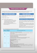
Balance quality of drive shaft If a rotating drive shaft is unbalanced, it may adversely influence the equipment and ambient conditions, thus posing a problem. JTEKT designs and manufactures drive shafts to satisfy the balance quality requirements specified in JIS B 0905. Expression of balance quality The balance quality is expressed by the following equation: Balance quality =eeu or Balance quality = en /9.55 where e: Amount of specific unbalance (mm) This amount is the quotient of the static unbalance of a rigid rotor by the rotor mass. The amount is equal to the deviation of the center of...
Open the catalog to page 11All KOYO BEARINGS VIERZON MAROMME (GROUPE JTEKT) catalogs and technical brochures
 Standard Bearings
241 Pages
 Ball & Roller Bearing
84 Pages
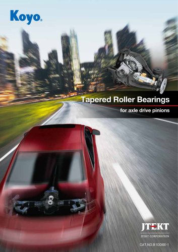
 TAPERED ROLLER BEARINGS
107 Pages
 Needle Roller Bearings
274 Pages
 LARGE SIZE BALL & ROLLER BEARINGS
247 Pages
Archived catalogs
 B1005E EXSEV Product Guidebook
13 Pages
 B1013E Ceramic Bearings
17 Pages
 B1011E Traction Drive Unit
4 Pages
 B2004E Ceramic & EXSEV
71 Pages
 B1021E Slim Bearing
2 Pages
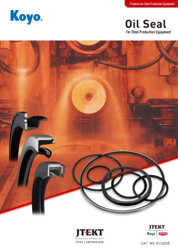
 Oil Seal & O-Ring
126 Pages
 Wind Turbine Generators
4 Pages
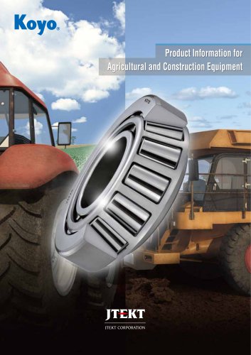
 Agriculture and Construction
6 Pages


- Ball bearing bearing
- Steel bearing
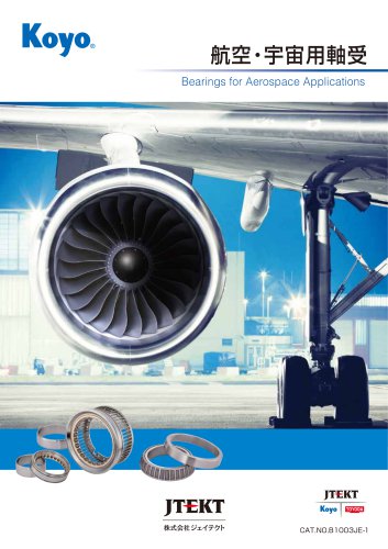
- Airliner bearing
- Roller bearing
- Precision bearing
- Radial bearing
- Single-row bearing
- Double-row bearing
- Heavy-duty bearing
- Pre-lubricated bearing
- Deep groove bearing
- Cylindrical roller bearing
- Axial bearing
- Self-aligning bearing
- Bearing with cage
- High-speed bearing
- Sealed bearing
- Stainless steel bearing
- Tapered roller bearing