- Catalogs
- Inertial Sense
- Calibrated Inertial Systems with GPS μIMU, μAHRS, μINS
Calibrated Inertial Systems with GPS μIMU, μAHRS, μINS

Calibrated Inertial Systems with GPS μIMU, μAHRS, μINS
- High update rate of up to 1KHz for IMU data.
- Synchronized attitude, velocity, and position data with UTC time.
- Dual redundant IMUs calibrated for bias, scale factor, and cross-axis alignment.
- Supports coning and sculling integrals for enhanced motion tracking.
- Equipped with barometric pressure and humidity sensors.
- Utilizes u-Blox L1 GPS (GNSS) receiver for accurate positioning.
- Operates in a wide temperature range from -40°C to 85°C.
- Configurable binary and NMEA protocol output.
- Fast integration with SDK and example software.
- Compact design suitable for drones, unmanned vehicles, and robotics.
- Drone navigation and unmanned vehicle payloads.
- Stabilized platforms and antenna/camera pointing.
- Tracking for first responders and personnel.
- Navigation for pedestrians and vehicles, both indoor and outdoor.
- Health, fitness, and sport monitoring devices.
- Hand-held devices and maritime applications.
The μIMU™ is a miniature sensor module integrating an IMU, magnetometer, barometer, and GPS receiver. It outputs data such as angular rate, linear acceleration, magnetic field, barometric altitude, and GPS geo-position. The μAHRS™ extends the μIMU™ capabilities by estimating roll, pitch, and heading. The μINS™ further includes GPS-aided inertial navigation, providing comprehensive orientation, velocity, and position data.
Specifications- Dynamic roll/pitch accuracy: 0.2°; heading: 0.5°.
- Static roll/pitch accuracy: 0.5°; heading: 2.0°.
- Horizontal position accuracy: 2.0 m; vertical: 2.5 m.
- Velocity accuracy: 0.05 m/s; angular resolution: 0.05°.
- Operational limits include velocity up to 500 m/s and altitude up to 50 km (GPS).
- Startup time is 0.8 seconds with GPS lock times of 1 second (hot start) and 30 seconds (cold start).
- GNSS receiver sensitivity ranges from -164 dBm for tracking to -147 dBm for cold start.
- Power consumption varies with configuration, with the μIMU consuming 340 mW at 1KHz.
The IMU updates at 1 KHz, with gyros and accelerometers sampled at higher rates and down-sampled. It is factory calibrated for various parameters to ensure optimal performance. Coning and sculling integrals are calculated and reset with each output.
Mechanical and Electrical Details- Compact size and lightweight design, with the μINS measuring 16.5 x 12.6 x 4.6 mm and weighing 1.3 grams.
- Supports multiple communication interfaces including TTL, SPI, I2C, USB, RS232, RS422, and RS485.
- Power supply requirements and pin definitions are detailed for integration purposes.
Various modules and development kits are available, including the IS-uINS, IS-uAHRS, and IS-uIMU, each with specific features and capabilities for different applications.
Physical DimensionsThe document specifies the dimensions of the modules and evaluation boards in millimeters, although exact measurements are not provided in the text.
Jumper ConfigurationThe evaluation board features hardware jumpers located on the bottom side. These jumpers configure RS485/RS422 features and select the serial port connection for USB. Key jumpers include:
- R9 RXEN: Enables receiver for RS232 and RS485 functions.
- R10 232: Selects between RS232 or RS485/RS422 mode.
- R8, R11, R12 S0 S1: Connects USB to either Ser0 or Ser1, requiring all three jumpers to move together.
Optional components for use with the systems include various GPS antennas and a GPS backup battery. Notable components are:
- Taoglas Limited AGGBP.25B.07.0060A: A two-stage GPS-Galileo-Glonass-BeiDou antenna module.
- Taoglas Limited AA.162.301111: A miniature magnet-mounted GPS-GLONASS antenna.
- Abracon LLC APAMPG-130: A GPS-GLONASS active antenna with 30dB gain.
- Panasonic ML-614S/FN: A rechargeable lithium battery.
The document includes a disclaimer regarding the use of Inertial Sense products, emphasizing that they are not suitable for automotive, military, or safety-critical applications without specific consent. It also disclaims liability for damages arising from the use of the document.
Catalog excerpts
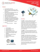
Calibrated Inertial Systems with GPS |iIMU, pAHRS, lilNS <t) INERTIALSENSE "i J micro navigation systems Features • Up to 1KHz IMU Update Rate • Attitude (Roll, Pitch, Yaw, Quaternions, DCM), Velocity, and Position (LLA, ECEF, NED) UTC Time Synchronized • Dual Redundant IMUs Calibrated for Bias, Scale Factor, and Cross-Axis Alignment • Coning & Sculling Integrals (A theta, A velocity) • Barometric Pressure and Humidity • u-Blox L1 GPS (GNSS) Receiver • -40°C to 85°C Temperature Compensation • Configurable binary and NMEA protocol output • Fast Integration using SDK and Example Software • Data Logging using SDK library and PC Software • Miniature Surface Mount Package: o 16.5 x 12.6 x 4.6 mm, 1.3 grams • EVB Case: o 40 x 33.2 x 15.8 mm, 19 grams Applications • Drone Navigation • Unmanned Vehicle Payloads • Stabilized Platforms • Antenna and Camera Pointing • First Responder and Personnel Tracking • Pedestrian and Auto Outdoor / Indoor Navigation • Health, Fitness, and Sport Monitors • Hand-held Devices • Robotics and Ground Vehicles • Maritime ^IMU™ ^AHRS™ ^INS™ The pIMU™ is a miniature calibrated sensor module consisting of an Inertial Measurement Unit (IMU), magnetometer, barometer, and L1 GPS (GNSS) receiver. Data out includes angular rate, linear acceleration, magnetic field, barometric altitude, and GPS WGS84 geoposition. All systems include a comprehensive sensor calibration for bias, scale-factor, and cross-axis alignment, minimizing manufacturing variation and maximizing system performance. The pAHRS™ is an Attitude Heading Reference System (AHRS) that includes all functionality of the pIMU™ and fuses IMU and magnetometer data to estimate roll, pitch, and heading. The pINS™ is a GPS (GNSS) aided Inertial Navigation System (GPS-INS) module that includes all functionality of the pAHRS™ and provides orientation, velocity, and position. Sensor data from MEMs gyros, accelerometers, magnetometers, barometric pressure, and GPS/GNSS is fused to provide optimal estimation. The patent-pending package is smaller than 3 stacked dimes and fits into most industrial and commercial application designs.
Open the catalog to page 1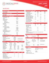
V "i J micro navigation systems Specifications Performance: (^INS) Typ Electrical (^INS, ^AHRS, ^IMU) Dynamic Roll/Pitch Dynamic Heading Performance (^INS, ^AHRS) Typ Static Roll/Pitch Static Heading Performance (^INS, ^AHRS, ^IMU) Horizontal Position (SBAS) Vertical Position Velocity Angular Resolution Operation Limits Velocity Altitude (GPS) Altitude (Barometric) Startup Time GPS Lock Time Hot Start Cold Start GNSS Receiver Sensitivity Tracking & Navigation Cold Start Hot Start GPS Update Rate Max Output Rate (pIMU, |_ti NS) Time Pulse Signal Accuracy RMS 99% Power Consumption Min pIMU @...
Open the catalog to page 2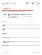
Calibrated Inertial Systems with GPS μIMU, μAHRS, and μINS Ordering Information Part Number Description IS-uINS GPS Aided Inertial Navigation System Module w/ Calibrated IMU IS-uAHRS Attitude Heading Reference System w/ L1 GNSS Receiver IS-uIMU Calibrated Inertial Measurement Unit w/ L1 GNSS Receiver Development Kits for fast and convenient integration and evaluation. IS-uINS-DK uINS GPS aided Inertial Navigation System with EVB interface board, semi-rugged case, and cables. IS-uAHRS-DK uAHRS Attitude Heading Reference System with EVB interface board, semi-rugged case, and cables for fast and...
Open the catalog to page 3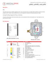
INERTIALSENSE micro navigation systems Calibrated Inertial Systems with GPS ^IMU, ^AHRS, and ^INS The inertial measurement unit (IMU) is updated at 1 KHz. Gyros and accelerometers are sampled at 8KHz and 4KHz respectively and downsampled to 1KHz. The IMU is factory calibrated for bias, cross-axis alignment, scale factor, and operating temperature range. Coning & Sculling Integrals (A Theta, A Velocity) Coning and sculling integrals, delta theta and delta velocity, are accumulated by the IMU at IMU update rates. These integrals are reset each time they are output. pIMU, pAHRS, and pINS Module...
Open the catalog to page 4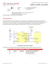
Calibrated Inertial Systems with GPS O Serial 0 output (RS232 or RS485/RS422 Tx+) O Serial 0 output (RS485/RS422 Tx-) - Leave unconnected GPIO pins G1 through G9 are configurable as general purpose digital inputs or outputs. *Available in future firmware update. tTied to FTDI USB to serial converter when USB is connected. Use Molex PicoBlade™ series connectors for the EVB headers. The following schematic demonstrates a typical setup for the ^INS module. A rechargeable lithium backup battery enables the GPS to perform a warm or hot start. If no backup battery is connected, GPS.VBAT should...
Open the catalog to page 5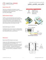
Calibrated Inertial Systems with GPS μIMU, μAHRS, and μINS System Status LED Status LED Orange Blue Green Red Pulse White / Purple System status including GPS lock, INS alignment, and time synchronization are reported via the top tri-color LED. This LED can be disabled (turned off) by setting bit 0x4 of DID_FLASH_CONFIG.sysCfgBits. Meaning INS not aligned INS aligned – No GPS lock INS aligned – w/ GPS lock GPS time synchronization Bootloader mode (Updating firmware) EVB (Evaluation Board) The EVB is a carrier board that provides a fast and convenient means to integrate and interface with the...
Open the catalog to page 6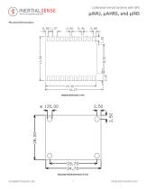
Calibrated Inertial Systems with GPS μIMU, μAHRS, and μINS Physical Dimensions Evaluation Board Dimensions in mm
Open the catalog to page 7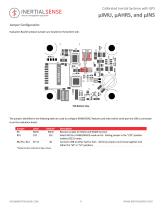
Calibrated Inertial Systems with GPS Evaluation Board hardware jumpers are located on the bottom side. The jumpers identified in the following table are used to configure RS485/RS422 features and select which serial port the USB is connected to on the evaluation board. Jumper Label Default* Receiver enable for RS232 and RS485 function. Select RS232 or RS485/RS422 mode on H5. Setting jumper in the "232" position enables RS232 mode. Connects USB to either Ser0 or Ser1. All three jumpers must move together into either the "S0" or "S1" positions. *Default location indicated in figure above.
Open the catalog to page 8