
Catalog excerpts
(Jl-TECH GROUP
Open the catalog to page 1
(Jl-TECH GROUP
Open the catalog to page 2
(Jl-TECH GROUP
Open the catalog to page 3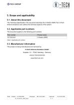
(Jl-TECH GROUP This Technical Specification (TS) document describes the H-Switch 4SRS from H-Tech Airborne Solutions and outlines the technical aspects of the system. This document applies to the following part numbers:
Open the catalog to page 4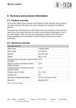
(Jl-TECH GROUP The H-Switch 4SRS system provides functionalities for video switching, video recording and video streaming. The system has various interfaces for integration into different platforms. The system has 4 SDI inputs and 4 SDI outputs, which are combined to a 4x4 switching matrix. Any of the 4 video inputs can be routed via user defined configurations to any of the 4 SDI outputs. Power over SDI can be separately activated for the 4 SDI inputs. Further possibilities and functionalities include recording, streaming and overlay functionality.
Open the catalog to page 5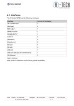
(Jl-TECH GROUP The H-Switch 4SRS has the following interfaces:
Open the catalog to page 6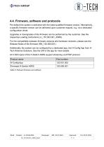
(Jl-TECH GROUP Per default the system is delivered with the latest qualified firmware version. Alternatively, a specific firmware version can be delivered upon customer request, e.g. via a dedicated configuration sheet. Upgrades or downgrades of the firmware can be performed by the customer. See the respective Loading Instructions (LI_157.003.001_4SRS). For the compatibility between firmware versions and hardware revisions, please see the Release Notes of the firmware (RN_120.000.001). Additionally, the system can be configured by a dedicated app, the H-Config App from H-Tech Airborne...
Open the catalog to page 7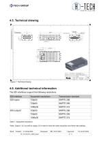
(Jl-TECH GROUP 4.6. Additional technical information The SDI interfaces support the following resolutions:
Open the catalog to page 8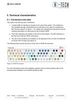
(Jl-TECH GROUP The system has three groups of interfaces. 1. A single USB 3.0 interface is located on the side of the system. This interface is only available through a dedicated service slot and is only used for maintenance. See "Service plate A” on figure 1. For update and maintenance instructions see the Loading Instructions (LI) document for the H-Switch 4SRS. 2. The 8 SDI interfaces are located on the front of the system. The SDI interfaces on the front are 8 Samtec DIN7A connectors. 3. The rest of the interfaces are installed on the backside of the unit with a D-SUB HD connector with...
Open the catalog to page 9
(Jl-TECH GROUP This chapter includes more details on the main functionalities of the H-Switch 4SRS. The system has 4 SDI inputs and 4 SDI outputs, which are combined to a 4x4 switching matrix. Any of the 4 video inputs can be routed via user defined configurations to any of the 4 SDI outputs. Power over SDI can be separately activated for the 4 SDI inputs by the user. The system can also be used as a landing aid system and display a crosshair projection on top of the rear camera image to help the pilots during landing phase. The system can provide 4 channel recording capabilities for all 4...
Open the catalog to page 10
(Jl-TECH GROUP All rights reserved. No part of this document may be reproduced or transmitted in any form or by any means, electronic or mechanical, including photocopying and recording, for any purpose without the express written permission of H-Tech Airborne Solutions. © by H-Tech Airborne Solutions GmbH
Open the catalog to page 11