- Catalogs
- Flight Display Systems
- FD90AID-7
FD90AID-7

FD90AID-7
The FD90AID-7 is a 7” Flip Down Controller designed to optimize cockpit space with a low-profile display for various video sources. It features a 90° "face-out" display and can be mounted on the top or bottom. The unit includes a torsion spring for deployment and an automatic power switch.
The display is a 7” TFT Color LCD with 800x480 resolution and 450 cd/m2 brightness. It supports 12VDC and 28VDC power inputs and various video formats including VGA and NTSC/PAL. The unit is DO160 tested and weighs 1 lb 8 oz.
The FD90AID-7 should be installed on a non-essential bus with a dedicated circuit breaker. Installation requires drilling and specific tools. Wiring should avoid parallel routing with noise sources.
Use PIC 75 Ohm Coax for composite video and ECS P/N 453005 for VGA wiring. Ensure proper grounding and avoid AC noise sources.
An optional swivel base (FD90AID-7-SWL) allows display rotation. For dual installations, use DAPS321 for composite signals and DAPS350 for VGA signals.
The unit powers on with 28VDC and searches for video input. Controls include power, source selection, and menu navigation.
Common issues include VGA shadowing, AC noise, and color distortion. Solutions involve checking wiring, adjusting settings, and ensuring proper grounding.
Contact Flight Display Systems at 470-239-7421 or visit their website for support.
Products are warranted for 24 months for General Aviation customers and 12 months for Government/Special Mission customers, with specific exclusions.
- Damage from unauthorized alterations.
- Signal issues from external noise.
- Malfunctions from improper installation or incompatible equipment.
- Damage from non-conforming installations to environmental precautions.
- Cosmetic or internal damage from improper handling.
- Products with tampered seals or modified labels void warranty.
Available Monday to Friday, 8:00am to 5:00pm EST at (470) 239-7421. Many issues can be resolved remotely. If return is necessary, an RMA number will be issued.
Available upon request for non-PMA products. Customer covers travel and technician costs.
Returned products may be remanufactured or replaced at FDS's discretion. Ground return shipping is covered by FDS; express shipping is sender's responsibility.
Non-transferable. Implied warranties expire with the express warranty. FDS not liable for indirect damages. State laws may affect warranty limitations.
Document Number: MAN – FD90AID-7, Revision: B, Revision Date: 10/29/2010.
- Rev A (10/21/2010): Initial Release.
- Rev B (10/29/2010): Updates to weight, button controls, DAPS350 info, and pinout info.
Catalog excerpts

Document Number: Revision Date: 10/29/2010 Page 1 of 16 Installation and Operation Manual FD90AID-7 7” Flip Down Controller © 2015 Flight Display Systems. All Rights Reserved. TECHNICAL SUPPORT 470-239-7421 or FlightDisplay.c
Open the catalog to page 1
Document Number: Revision Date: 10/29/2010 Page 2 of 16 FD90AID-7 7” Flip Down Controller © 2010 Flight Display Systems. All Rights Reserved. Flight Display Systems 6435 Shiloh Road Alpharetta, GA 30005 470-239-7400 Phone 678-867-6742 Fax [email protected] www.FlightDisplay.com For the most current copy of all product manuals, please visit our website at www.FlightDisplay.com © 2015 Flight Display Systems. All Rights Reserved. TECHNICAL SUPPORT 470-239-7421 or FlightDisplay.
Open the catalog to page 2
Document Number: Revision Date: 10/29/2010 Page 3 of 16 © 2015 Flight Display Systems. All Rights Reserved. TECHNICAL SUPPORT 470-239-7421 or FlightDisplay.com
Open the catalog to page 3
Document Number: Revision Date: 10/29/2010 Page 4 of 16 General Information The FD90AID-7 is a 7” Flip Down Controller, which creates panel space where none previously existed, providing an excellent opportunity to bring EVS video, satellite weather, or any other VGA Composite source into the cockpit with a low-profile, stowing display. Front View Additional Information The FD90AID-7 features a “face-out” display, which the pilot would open 90° to be viewed. The FD90AID is available in top or bottom mount configurations. The 7” flip display is available in a top mount (FD90AID-7-T) for mounting...
Open the catalog to page 4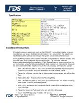
Document Number: Revision Date: 10/29/2010 Page 5 of 16 Specifications Display Type Screen Resolution Brightness Overall Dimensions Power Video Inputs Supported Video Types Supported Screen Control DO160 TESTED Weight Materials 7” TFT Color LCD 800x480 450 cd/m2 Open: 7.8”(W) x 4.7”(H) x 5.0”(D) Closed: 7.8” (W) x .89” (H) x 5.0” (D) 12VDC @ .6AMPS 28VDC @ .3 AMPS (1) Analog RGB, (2) Composite Video VGA, NTSC/PAL On Screen Display Menu Section 21, Category B 1 lb 8 oz Aluminum Installation Instructions All cockpit accessory equipment, such as the FD90AID-7, should be installed on a nonessential...
Open the catalog to page 5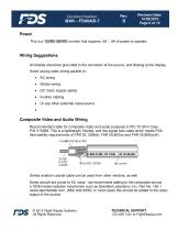
Document Number: Revision Date: 10/29/2010 Page 6 of 16 Power This is a 12VDC-28VDC monitor that requires .5A - .3A of power to operate. Wiring Suggestions All shields should be grounded to the connector at the source, and floating at the display. Avoid routing video wiring parallel to: Strobe wiring DC motor supply cables Inverter cabling Or any other potential noise source. Composite Video and Audio Wiring Recommended cable for composite video and audio purposes is PIC 75 Ohm Coax, P/N V75268. This is a lightweight, flexible, and low signal loss cable which meets FAA flammability requirements...
Open the catalog to page 6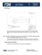
Document Number: Revision Date: 10/29/2010 Page 7 of 16 Recommended cable for VGA purpose is ECS P/N 453005. This is a single shielded cable containing 5 separate coaxial cables, color-coded to match the functions of the wires. Note: The above illustration is generic; the pin-out for the wiring on this particular unit is a straight through cable (1-1, 2-2, etc). The individual wires should be extended with 6” 22awg wires using an environmental splice for the red & green wires, and Raychem caps for the blue, white, and black wires. Power and Ground Wiring 22 AWG wire is recommended for Power and...
Open the catalog to page 7
Document Number: Revision Date: 10/29/2010 Page 8 of 16 Additional Options Swivel Base An optional swivel base, FD90AID-7-SWL, is available which allows the user to rotate the display inboard & outboard. The swivel base is mounted directly to the existing mounting plate and allows the FD90AID-7 to rotate left and right. The swivel base assembly adds approximately 0.175” to the total height of the unit. © 2015 Flight Display Systems. All Rights Reserved. TECHNICAL SUPPORT 470-239-7421 or FlightDisplay.c
Open the catalog to page 8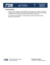
Document Number: Revision Date: 10/29/2010 Page 9 of 16 Dual Installation As with all of our displays, multiple FD90AID-7 configurations are possible. A DAPS321 is used to split and amplify the composite signal to multiple units. For computer graphics, a DAPS350 is used to split and amplify the VGA signal to multiple units. For assistance with installation of multiple displays, please contact Flight Display Systems at 470-239-7400.. © 2015 Flight Display Systems. All Rights Reserved. TECHNICAL SUPPORT 470-239-7421 or FlightDisplay.com
Open the catalog to page 9
Document Number: Revision Date: 10/29/2010 Page 10 of 16 Pinouts for High Density DB-15 Part Numbers for DB-15 connectors, manufactured by Tyco or Amp. High density, D-sub, 15 contact plug (Male) Description Power 28V + Power 28V N/C Composite Video #1 Signal Composite Video #1 - Shield N/C Composite Video #2 - Signal Composite Video #2 - Shield Red Video (RGB/VGA) Green Video (RGB/VGA) Blue Video (RGB/VGA) Red Ground (RGB/VGA) Green Ground (RGB/VGA) Horizontal Sync (RGB/VGA) Vertical Sync (RGB/VGA) © 2015 Flight Display Systems. All Rights Reserved. TECHNICAL SUPPORT 470-239-7421 or FlightDisplay.com...
Open the catalog to page 10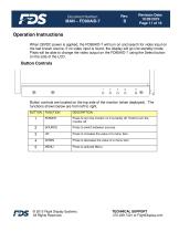
Document Number: Revision Date: 10/29/2010 Page 11 of 16 Operation Instructions When 28VDC power is applied, the FD90AID-7 will turn on and search for video input on the last known source. If no video input is found, the display will go into standby mode. Pilots will be able to change the video output on the FD90AID-7 using the Select button on the side of the LCD. Button Controls Button controls are located on the top side of the monitor (when deployed). The functions shown below are from left to right. BUTTON Press to turn the monitor on if currently off. Hold to turn the monitor off. Press...
Open the catalog to page 11
Document Number: Revision Date: 10/29/2010 Page 12 of 16 Troubleshooting VGA Shadowing Most of shadowing problems are due to shielding on the wire. Locate the point where all of the shields are connected. Cut away the shields, one at a time, while viewing the display on the screen to observe which shield is causing the noise. Cutting away one shield at a time will allow you to focus and isolate the video noise issue. Twisted pair wiring is prone to video noise. ECS VGA Wire (Detailed under “Video Wiring Suggestions”) is recommended. Snow or Sweeping Lines Lines that slowly sweep up and down...
Open the catalog to page 12All Flight Display Systems catalogs and technical brochures
 FD201CV-LP
20 Pages
 FD141CV
18 Pages
 FD102CV
16 Pages
 FD70CV
14 Pages
 smart cabin CMS BROCHURE
12 Pages
 helicopter CMS Brochure
2 Pages
 why FDS
2 Pages
 the new FDS
2 Pages
 do capsule
2 Pages