- Catalogs
- Flight Display Systems
- FD201CV-LP
FD201CV-LP

FD201CV-LP
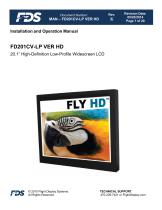
The FD201CV-LP VER HD is a 20.1" high-definition low-profile widescreen LCD designed for retrofit aircraft integration. It supports five video input sources and can be controlled via an infrared remote.
- Display Type: 20.1” TFT Color LCD
- Resolution: 1600x1200 UGA
- Brightness: 450 cd/m2
- Dimensions: 18.00”(W) x 15.13”(H) x 1.65”(D)
- Weight: 12lbs. 9 oz.
- Power: 28V DC @ 3.0A
- Operating Temperature: 0-50° C
- Inputs: VGA, S-Video, Composite, HDMI (2)
- Viewing Angle: 176° on both axes
- Materials: Aluminum
- Remote Control: IR included
The display should be installed on a non-essential bus with a dedicated circuit breaker. A cockpit switch is required for de-energizing the system. Ensure proper ventilation with at least a ¼” gap for cooling.
- Power: 28VDC, 3.0 Amps
- Recommended cables: PIC 75 Ohm Coax for S-Video/Composite, ECS P/N 453005 for VGA
- RS-485: Shielded twisted-pair 22 AWG wire
- HDMI: ECS cable, part number 600-19786-XXX
RS-485 allows remote control of the monitor's functions. Up to 99 monitors can be controlled by one unit. The system should be set up for 19200 Baud, no parity, 8 bits of data, and 1 stop bit.
The display is continuously on and can be de-energized by removing power. Video output can be changed using the display's button or the IR remote. The display will enter standby mode if no valid input is detected.
Common issues include VGA shadowing, snow or sweeping lines, no power or video input, and color distortion. Solutions involve checking wiring, adjusting settings, and ensuring proper grounding. Specific recommendations include using ECS VGA Wire for video noise and verifying video source operation.
For assistance, contact Flight Display Systems at 470-239-7421 or visit FlightDisplay.com. The company provides remote troubleshooting and may issue an RMA for returns. Onsite repairs for non-PMA products are available at the customer's expense.
FDS products are warranted against defects for 24 months (General Aviation) or 12 months (Government/Special Mission). Exclusions include labor costs, unauthorized alterations, and improper installation. Warranty is void if tamper-evident seals are broken.
The document has undergone multiple revisions, with updates to specifications, warranty information, and technical drawings. The latest revision (K) includes changes to address, warranty information, and RS-485 Command Set.
Catalog excerpts
Document Number: Revision Date: 05/23/2014 Page 1 of 20 Installation and Operation Manual FD201CV-LP VER HD 20.1” High-Definition Low-Profile Widescreen LCD © 2015 Flight Display Systems. All Rights Reserved. TECHNICAL SUPPORT 470-239-7421 or FlightDisplay.c
Open the catalog to page 1
Document Number: Revision Date: 05/23/2014 Page 2 of 20 FD201CV-LP VER HD 20.1" High-Definition Low-Profile Widescreen LCD © 2014 Flight Display Systems. All Rights Reserved. Flight Display Systems 6435 Shiloh Road Alpharetta, GA 30005 470-239-7400 Phone 678-867-6742 Fax [email protected] www.FlightDisplay.com For the most current copy of all product manuals, please visit our website at www.FlightDisplay.com For additional support, please visit our Frequently Asked Questions section located on our web site Support Center at http://support.FlightDisplay.com. © 2015 Flight Display Systems....
Open the catalog to page 2
Document Number: Revision Date: 05/23/2014 Page 3 of 20 TECHNICAL SUPPORT 470-239-7421 or FlightDisplay.com
Open the catalog to page 3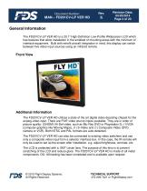
Document Number: Revision Date: 05/23/2014 Page 4 of 20 General Information The FD201CV-LP VER HD is a 20.1" High-Definition Low-Profile Widescreen LCD which has features that allow installation in the smallest of mounting areas with the minimum of interface equipment. Built with retrofit aircraft integration in mind, this display can switch between five video input sources using an infrared remote. Front View Additional Information The FD201CV-LP VER HD utilizes a state of the art digital video decoding chipset for the analog video input. There are FIVE video source inputs available. They are...
Open the catalog to page 4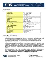
Document Number: Revision Date: 05/23/2014 Page 5 of 20 Specifications Display Type Display Color Screen Resolution Brightness Dimensions Display Size Weight Power Operating Temperature PC&Video Input Video Type Supported Screen Control Viewing Angle Materials DO-160 Testing Remote Control Pixel Pitch 20.1” TFT Color LCD 16.7 Million Colors 1600x1200 UGA 450 cd/m2 18.00”(W) x 15.13”(H) x 1.65”(D) 16.1”(W) x 12.1”(H) 12lbs. 9 oz. 28V DC @ 3.0A 0-50° C (32-122° F) VGA (high-Density DB-15 Connector), S-Video, Composite, HDMI (2) NTSC/PAL On-Screen Display Menu 176 on Both Axis Aluminum Section...
Open the catalog to page 5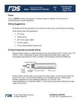
Document Number: Revision Date: 05/23/2014 Page 6 of 20 Power This is a 28VDC monitor that requires 3.0 Amps of power to operate. The unit turns on automatically upon power application. Wiring Suggestions All shields should be grounded to the connector at the source, and floating at the display. Avoid routing video wiring parallel to: Strobe wiring DC motor supply cables Inverter cabling Or any other potential noise source. S-Video/Composite and Audio Wiring Recommended cable for s-video/composite and audio purposes is PIC 75 Ohm Coax, P/N V76261. This is a lightweight, flexible, and low signal...
Open the catalog to page 6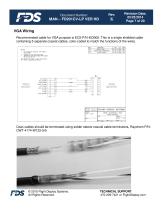
Document Number: Revision Date: 05/23/2014 Page 7 of 20 VGA Wiring Recommended cable for VGA purpose is ECS P/N 453005. This is a single shielded cable containing 5 separate coaxial cables, color-coded to match the functions of the wires. Coax cables should be terminated using solder sleeve coaxial cable terminators, Raychem P/N: CWT-4174-W122-5/9 © 2015 Flight Display Systems. All Rights Reserved. TECHNICAL SUPPORT 470-239-7421 or FlightDisplay.com
Open the catalog to page 7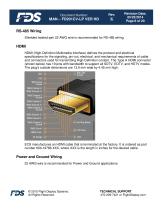
Document Number: Revision Date: 05/23/2014 Page 8 of 20 RS-485 Wiring Shielded twisted-pair 22 AWG wire is recommended for RS-485 wiring. HDMI HDMI (High-Definition Multimedia Interface) defines the protocol and electrical specifications for the signaling, pin-out, electrical, and mechanical requirements of cable and connectors used for transmitting High-Definition content. The Type A HDMI connector (shown below) has 19 pins with bandwidth to support all SDTV, EDTV, and HDTV modes. The plug's outside dimensions are 13.9 mm wide by 4.45 mm high. ECS manufactures an HDMI cable that is terminated...
Open the catalog to page 8
Document Number: Revision Date: 05/23/2014 Page 9 of 20 Power/Video Pin out for P1 (High Density DB-15 Receptacle) Connector Crimp Contacts Description 28VDC Power 28VDC Ground Composite Video - Signal Composite Video - Shield S-Video Y - Signal S-Video Y - Shield S-Video C - Signal S-Video C - Shield Red Video (Pin 1 on Standard VGA) Green Video (Pin 2 on Standard VGA) Blue Video (Pin 3 on Standard VGA) Red Ground (Pin 6 on Standard VGA) Green Ground (Pin 7 on Standard VGA) Horizontal Sync (Pin 13 on Standard VGA) Vertical Sync (Pin 14 on Standard VGA) © 2015 Flight Display Systems. All Rights...
Open the catalog to page 9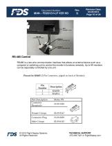
Document Number: Revision Date: 05/23/2014 Page 10 of 20 RS-485 Control RS485 is a two-wire communication interface that allows an external device such as a computer or switching unit to control the monitor’s functions remotely. Up to 99 monitors can be separately controlled by one unit. Pinout for RS485 (2-Pin Connector, pigtail on back of Monitor) Part Description Connector Receptacle Female Crimps Connector Plug Male Crimps © 2015 Flight Display Systems. All Rights Reserved. TECHNICAL SUPPORT 470-239-7421 or FlightDisplay.c
Open the catalog to page 10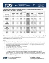
Document Number: Revision Date: 05/23/2014 Page 11 of 20 Command sets for controlling the monitors with serial numbers starting w/ 12XXXXXXXX (10 digits) and above: Commands Length HDMI 1 HDMI 2 DVI VGA S-Video Composite Auto Full Screen 16:9 4:3 Below are the command sets to control the power, source selection, and backlight brightness. The 13 characters below are shown in hexadecimal. The communication system must be set up for 19200 Baud, no parity, 8 bits of data, and 1 stop bit. Notes: 1. The first nine characters will remain the same for any command. 2. For connecting multiple monitors...
Open the catalog to page 11
Document Number: Revision Date: 05/23/2014 Page 12 of 20 RS-485 Network: If there is more than one monitor connected to the aircraft’s RS-485 controller system, then it is strongly recommended to connect the system in series, or daisy-chain, and terminate the twisted pairs with a 120 OHM resistor. This configuration improves the reliability of the system. It is highly recommended to use 22 AWG twisted pairs for runs longer than 20 feet. Connect all RS-485 A pins together, all RS-485 B pins together. © 2015 Flight Display Systems. All Rights Reserved. TECHNICAL SUPPORT 470-239-7421 or FlightDisplay.c...
Open the catalog to page 12All Flight Display Systems catalogs and technical brochures
 FD90AID-7
16 Pages
 FD141CV
18 Pages
 FD102CV
16 Pages
 FD70CV
14 Pages
 smart cabin CMS BROCHURE
12 Pages
 helicopter CMS Brochure
2 Pages
 why FDS
2 Pages
 the new FDS
2 Pages
 do capsule
2 Pages