FD141CV

FD141CV
The FD141CV is a 14.1” widescreen LCD designed for aircraft retrofit integration, suitable for compact spaces with minimal interface equipment. It supports switching between three video input sources via an infrared remote.
- Display Type: 14.1” WXGA High Bright TFT-LCD
- Resolution: 1280 x 800 pixels
- Brightness: 1000 cd/m2
- Power: 28V DC @ 1.0A
- Inputs: VGA, Composite, S-Video
- Supported Video Types: NTSC/PAL
- Operating Temperature: -30° C to +80° C
The FD141CV should be installed on a non-essential bus with a dedicated circuit breaker. A cockpit switch is necessary to de-energize the system if needed. The display can be mounted using fourteen #8-32 mounting holes, ensuring adequate air circulation.
The monitor operates on 28VDC and requires 1 amp. Wiring should avoid parallel routing with potential noise sources. Recommended cables include PIC 75 Ohm Coax for video and ECS P/N 453005 for VGA.
The display is continuously on and can be controlled via an IR remote or onboard buttons. It automatically powers on with 28VDC and searches for the last known input source.
Common issues include VGA shadowing due to shielding problems and AC noise causing sweeping lines. Solutions involve adjusting shielding and grounding locations.
For further assistance, contact Flight Display Systems at 470-239-7421 or visit FlightDisplay.com. The technical support team is available Monday through Friday, 8:00 am to 5:00 pm EST.
Flight Display Systems products are warranted against material or manufacturing defects for 24 months for General Aviation customers and 12 months for Government/Special Mission customers. Exclusions include labor costs, unauthorized alterations, signal quality issues from external noise, improper installation, and tampering. The warranty is non-transferable and does not cover indirect or consequential damages.
The FD141CV is designed to require no regular general maintenance.
Revisions from A to G include specification updates, format changes, warranty updates, and additional technical information such as VGA wiring suggestions and button descriptions.
Catalog excerpts

Document Number: Revision Date: 10/31/2014 Page 1 of 18 Installation and Operation Manual © 2015 Flight Display Systems. All Rights Reserved. TECHNICAL SUPPORT 470-239-7421 or FlightDisplay.c
Open the catalog to page 1
Document Number: Revision Date: 10/31/2014 Page 2 of 18 © 2014 Flight Display Systems. All Rights Reserved. Flight Display Systems 6435 Shiloh Road Alpharetta, GA 30005 470-239-7400 Phone 678-867-6742 Fax [email protected] www.FlightDisplay.com For the most current copy of all product manuals, please visit our website at www.FlightDisplay.com For additional support, please visit our Frequently Asked Questions section located on our web site Support Center at http://support.FlightDisplay.com. © 2015 Flight Display Systems. All Rights Reserved. TECHNICAL SUPPORT 470-239-7421 or FlightDisplay....
Open the catalog to page 2
Document Number: Revision Date: 10/31/2014 Page 3 of 18 © 2015 Flight Display Systems. All Rights Reserved. TECHNICAL SUPPORT 470-239-7421 or FlightDisplay.com
Open the catalog to page 3
Document Number: Revision Date: 10/31/2014 Page 4 of 18 General Information The FD141CV is a 14.1” LCD which has features that allow installation in the smallest of mounting areas with the minimum of interface equipment. Built with retrofit aircraft integration in mind, this display can switch between three video input sources using an infrared remote. Front View Additional Information The FD141CV utilizes a state of the art digital video decoding chipset for the analog video input. The three video sources in order of picture quality are VGA (computer graphics like moving maps), S-Video and Composite...
Open the catalog to page 4
Document Number: Revision Date: 10/31/2014 Page 5 of 18 Specifications Display Type Display Color Screen Resolution Brightness Dimensions Display Size Weight Power PC &Video Input Video Type Supported Screen Control Materials DO-160 Testing Remote Control Pixel Pitch Operating Temperature Storage Temperature 14.1” WXGA High Bright TFT-LCD 262,000 Colors 1280 x 800 pixels 1000 cd/m2 13.40”(W) x 9.93”(H)x1.50”(D) 11.88”(W) x 7.40”(H) 6.0 lbs 28V DC @ 1.0A VGA, Composite, S-Video NTSC/PAL On-Screen Display Menu Aluminum Section 21, Category B Section 7, Category B IR, included 0.237 mm x 0.237 mm...
Open the catalog to page 5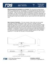
Document Number: Revision Date: 10/31/2014 Page 6 of 18 Mounting against the bulkhead or on a bracket: The unit can be mounted internal, external, or partially internal to the bulkhead. It is recommended that you leave about ¼ inch of space around the rear, top and bottom of the display for the exhaust fan to have circulating air. When mounting from inside the bulkhead it is possible to have only the LCD visible to the cabin. The unit will power on automatically upon power application and if using an external video source selection box the IR is not needed. If you are using the IR to change the...
Open the catalog to page 6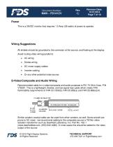
Document Number: Revision Date: 10/31/2014 Page 7 of 18 Power This is a 28VDC monitor that requires 1.0 Amp (28 watts) of power to operate. Wiring Suggestions All shields should be grounded to the connector at the source, and floating at the display. Avoid routing video wiring parallel to: Strobe wiring DC motor supply cables Inverter cabling Or any other potential noise source. S-Video/Composite and Audio Wiring Recommended cable for s-video/composite and audio purposes is PIC 75 Ohm Coax, P/N V76261. This is a lightweight, flexible, and low signal loss cable which meets FAA flammability requirements...
Open the catalog to page 7
Document Number: Revision Date: 10/31/2014 Page 8 of 18 VGA Wiring Recommended cable for VGA purpose is ECS P/N 453005. This is a single shielded cable containing 5 separate coaxial cables, color-coded to match the functions of the wires. Coax cables should be terminated using solder sleeve coaxial cable terminators, Raychem P/N: CWT-4174-W122-5/9 © 2015 Flight Display Systems. All Rights Reserved. TECHNICAL SUPPORT 470-239-7421 or FlightDisplay.com
Open the catalog to page 8
Document Number: Revision Date: 10/31/2014 Page 9 of 18 Power and Ground Wiring This is a 28VDC monitor that requires 1 amp of power to operate. To operate properly this monitor requires an input voltage of 24-29VDC. The rated current of the equipment and associated voltage drop should be taken into consideration when selecting wire gauge. The following example is based on an install with a 28VDC power system and a total of 50 feet of wire between the circuit breaker, monitor and ground. Example: 22awg wire has 16.2 Ohms per 1000 feet, this equates to .81 Ohms for 50 feet. 1 Amp of current on...
Open the catalog to page 9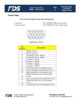
Document Number: Revision Date: 10/31/2014 Page 10 of 18 Power/Video Pin out for P1 (High Density DB-15 Receptacle) Connector Crimp Contacts Description 28VDC Power 28VDC Ground Composite Video - Signal Composite Video - Shield S-Video Y - Signal S-Video Y - Shield S-Video C - Signal S-Video C - Shield Red Video (Pin 1 on Standard VGA) Green Video (Pin 2 on Standard VGA) Blue Video (Pin 3 on Standard VGA) RGB Ground (Pins 6,7,8 on Standard VGA) Sync Ground (Pin 10 on Standard VGA) Horizontal Sync (Pin 13 on Standard VGA) Vertical Sync (Pin 14 on Standard VGA) © 2015 Flight Display Systems. All...
Open the catalog to page 10
Document Number: Revision Date: 10/31/2014 Page 11 of 18 Operation Instructions The FD141CV is continuously on but can be de-energized by removing power from the entertainment system. No pilot or aircrew action is necessary during flight or ground operation. The passengers will be able to change the video output from the FD141CV using the video source select button on the display, or remotely throughout the cabin with the included IR remote. Point the IR remote at the top of the LCD to make changes. When applying 28VDC power, the display will turn on and look for a valid input on the last known...
Open the catalog to page 11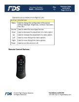
Document Number: Revision Date: 10/31/2014 Page 12 of 18 Operations are as follows (From Right to Left): BUTTON Used to change the configuration of the picture settings (Backlight, Brightness, Contrast, Saturation, Hue, etc.) Used to select the input signal source. Used to decrease the adjustment of a menu option. Used to increase the adjustment of a menu option. Used to move through the menu options. Used to move through the menu options. Used to turn the unit on or off. Remote Control Buttons © 2015 Flight Display Systems. All Rights Reserved. TECHNICAL SUPPORT 470-239-7421 or FlightDisplay.com...
Open the catalog to page 12All Flight Display Systems catalogs and technical brochures
 FD90AID-7
16 Pages
 FD201CV-LP
20 Pages
 FD102CV
16 Pages
 FD70CV
14 Pages
 smart cabin CMS BROCHURE
12 Pages
 helicopter CMS Brochure
2 Pages
 why FDS
2 Pages
 the new FDS
2 Pages
 do capsule
2 Pages