FD102CV

FD102CV
This document serves as an installation and operation manual for the FD102CV, a 10.2” widescreen LCD designed for aircraft cabin video and graphical entertainment. It supports three video input sources and can be controlled via an infrared remote or control buttons.
The FD102CV features a 10.2” widescreen TFT color LCD with a resolution of 1024x600, supporting up to 1600x1200. It has a brightness of 300 cd/m² and a contrast ratio of 500:1. The display dimensions are 9.8” x 6.32” x 1.04”, and it weighs 2 lbs 3 oz. It operates on 28VDC at 0.3 Amps and supports NTSC/PAL video types.
The monitor should be installed on a non-essential bus with a dedicated circuit breaker. A cockpit switch is required to de-energize the system if necessary. Ensure approximately ¼ inch of space around the rear for air circulation.
Use PIC 75 Ohm Coax for S-Video/Composite and audio wiring, and ECS P/N 453005 for VGA wiring. Ground all shields at the source and avoid routing video wiring parallel to potential noise sources.
The FD102CV is always on but can be de-energized by removing power. Passengers can change video output using the monitor's source select switch or the IR remote.
Common issues include VGA shadowing, AC noise, and color distortion. Solutions involve checking wiring, adjusting settings, and ensuring proper grounding.
For assistance, contact Flight Display Systems at 470-239-7421 or visit their website. Support is available Monday to Friday, 8:00am to 5:00pm EST. Distance troubleshooting is preferred; RMA required for returns. Onsite repairs for non-PMA products are customer-expensed.
The product is warranted for 24 months for general aviation customers and 12 months for government customers, excluding labor costs for installation or damage due to misuse. Unauthorized alterations void the warranty. Signal issues from external noise or improper connections are not covered. Malfunctions from non-compliant installations or environmental conditions are excluded. Cosmetic or internal damage from misuse or improper handling is not covered. Broken tamper seals void the warranty. Warranty is non-transferable.
FDS may remanufacture or replace returned units. Ground return shipping is covered; express shipping is sender's responsibility.
Multiple revisions from 2007 to 2012, including updates to specifications, drawings, and troubleshooting guides.
Catalog excerpts

Document Number: Revision Date: 02/01/2012 Page 1 of 16 Installation and Operation Manual © 2015 Flight Display Systems. All Rights Reserved. TECHNICAL SUPPORT 470-239-7421 or FlightDisplay.c
Open the catalog to page 1
Document Number: Revision Date: 02/01/2012 Page 2 of 16 © 2006 Flight Display Systems. All Rights Reserved. Flight Display Systems 6435 Shiloh Road Alpharetta, GA 30005 470-239-7400 Phone 678-867-6742 Fax [email protected] www.FlightDisplay.com For the most current copy of all product manuals, please visit our website at www.FlightDisplay.com © 2015 Flight Display Systems. All Rights Reserved. TECHNICAL SUPPORT 470-239-7421 or FlightDisplay.
Open the catalog to page 2
Document Number: Revision Date: 02/01/2012 Page 3 of 16 © 2015 Flight Display Systems. All Rights Reserved. TECHNICAL SUPPORT 470-239-7421 or FlightDisplay.com
Open the catalog to page 3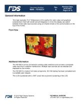
Document Number: Revision Date: 02/01/2012 Page 4 of 16 General Information This high resolution 10.2” Widescreen LCD is perfect for cabin video and graphical entertainment. Built with retrofit aircraft integration in mind, this display can switch between three video input sources using an infrared remote or the control buttons on the top of the monitor. Front View Additional Information The FD102CV can be connected to existing video switchers and can take a composite video input from a selector interface box. Multiple input sources can be selected and displayed on the monitor. The FD102CV is...
Open the catalog to page 4
Document Number: Revision Date: 02/01/2012 Page 5 of 16 Specifications Display Type Pixel Pitch Screen Resolution Supported Resolution Brightness Contrast Display Dimension Display Size Weight Power Operating Temperature Storage Temperature PC & Video Input Video Type Supported Screen Control Remote Control Materials Aspect Ratio DO-160 Testing 10.2” Widescreen TFT Color LCD 0.072 mm X 0.220 mm 1024x600 Up to 1600x1200 300 cd/ m² 500 : 1 9.8”(W) x 6.32” (H) x 1.04” (D) 8.70”(W) x 5.215” (H) 2 lbs 3 oz 28VDC @ 0.3 Amp -20°C/60°C -30°C/70°C VGA (Analog RGB 15 pin D-sub) 2 Composite Video NTSC/PAL...
Open the catalog to page 5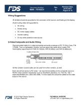
Document Number: Revision Date: 02/01/2012 Page 6 of 16 Wiring Suggestions All shields should be grounded to the connector at the source, and floating at the display. Avoid routing video wiring parallel to: Strobe wiring DC motor supply cables Inverter cabling Or any other potential noise source. S-Video/Composite and Audio Wiring Recommended cable for s-video/composite and audio purposes is PIC 75 Ohm Coax, P/N V75268. This is a lightweight, flexible, and low signal loss cable which meets FAA flammability requirements of FAR 23.1359(d), FAR 25.853(a) and FAR 25.869(a)(4). Similar aviation...
Open the catalog to page 6
Document Number: Revision Date: 02/01/2012 Page 7 of 16 VGA Wiring Recommended cable for VGA purpose is ECS P/N 453005. This is a single shielded cable containing 5 separate coaxial cables, color-coded to match the functions of the wires. Coax cables should be terminated using solder sleeve coaxial cable terminators, Raychem P/N: CWT-4174-W122-5/9 © 2015 Flight Display Systems. All Rights Reserved. TECHNICAL SUPPORT 470-239-7421 or FlightDisplay.com
Open the catalog to page 7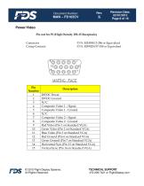
Document Number: Revision Date: 02/01/2012 Page 8 of 16 Power/Video Pin out for P1 (High Density DB-15 Receptacle) Connector Crimp Contacts Description 28VDC Power 28VDC Ground N/C Composite Video 1 – Signal Composite Video 1 - Ground N/C Composite Video 2 – Signal Composite Video 2 - Ground Red Video (Pin 1 on Standard VGA) Green Video (Pin 2 on Standard VGA) Blue Video (Pin 3 on Standard VGA) Red Ground (Pin 6 on Standard VGA) Green Ground (Pin 7 on Standard VGA) Horizontal Sync (Pin 13 on Standard VGA) Vertical Sync (Pin 14 on Standard VGA) © 2015 Flight Display Systems. All Rights Reserved....
Open the catalog to page 8
Document Number: Revision Date: 02/01/2012 Page 9 of 16 Operation Instructions The FD102CV is continuously on but can be de-energized by removing power from the entertainment system. No pilot or aircrew action is necessary during flight or ground operation. Passengers can change the video output from the FD102CV using the video source select switch on the LCD monitor, or remotely throughout the cabin with the included IR remote. Button Controls Press to turn the monitor on if currently off. Hold to turn the monitor off. Press to switch between sources. Press to increase the value of a menu item....
Open the catalog to page 9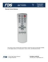
Document Number: Revision Date: 02/01/2012 Page 10 of 16 Remote Control Buttons The remote control included with the FD102CV contains the same functionality available on the display buttons, to include power, source, menu, and directional arrows. © 2015 Flight Display Systems. All Rights Reserved. TECHNICAL SUPPORT 470-239-7421 or FlightDisplay.com
Open the catalog to page 10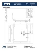
Document Number: Revision Date: 02/01/2012 Page 11 of 16 Technical Drawing © 2015 Flight Display Systems. All Rights Reserved. TECHNICAL SUPPORT 470-239-7421 or FlightDisplay.com
Open the catalog to page 11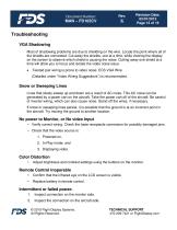
Document Number: Revision Date: 02/01/2012 Page 12 of 16 Troubleshooting VGA Shadowing Most of shadowing problems are due to shielding on the wire. Locate the point where all of the shields are connected. Cut away the shields, one at a time, while viewing the display on the screen to observe which shield is causing the noise. Cutting away one shield at a time will allow you to focus and isolate the video noise issue. Twisted pair wiring is prone to video noise. ECS VGA Wire (Detailed under “Video Wiring Suggestions”) is recommended. Snow or Sweeping Lines Lines that slowly sweep up and down...
Open the catalog to page 12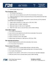
Document Number: Revision Date: 02/01/2012 Page 13 of 16 Confirm proper rating on fuses. Turn monitor off and back on. Cycle monitor source selections and confirm the functionality of the sources. 3. Inspect connection(s) to monitor to assure that they are firmly attached and that there are no damaged pins. 4. Inspect connections to/from the video splitter to assure that they are firmly attached and that there are no damaged pins. 5. Inspect output connections on video source. (DVD, BLU, PED) Adjust gain/output on splitter if applicable. Adjust gain/output on video source if applicable. Utilize...
Open the catalog to page 13All Flight Display Systems catalogs and technical brochures
 FD90AID-7
16 Pages
 FD201CV-LP
20 Pages
 FD141CV
18 Pages
 FD70CV
14 Pages
 smart cabin CMS BROCHURE
12 Pages
 helicopter CMS Brochure
2 Pages
 why FDS
2 Pages
 the new FDS
2 Pages
 do capsule
2 Pages