- Catalogs
- Fischer Connectors
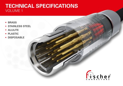
- Technical Specifications Volume 2
Technical Specifications Volume 2

Technical Specifications Volume 2
The document outlines technical specifications for Fischer connectors, including ULTIMATE, FIBEROPTIC, MINIMAX, and FREEDOM series. It covers connector overviews, cross-product specifications, and cable assembly details.
Each series offers unique features such as ruggedness, compactness, lightweight design, robustness, optical performance, easy cleaning, high-density miniaturization, high-speed data transfer, reliability, easy mating, and integration.
Connectors feature various locking mechanisms like push-pull, quick-release, and screw-locking. They are constructed from materials such as brass, aluminum, and stainless steel, with different plating options. They support a range of plug diameters, contact numbers, and wire gauges.
Connectors provide different sealing levels, including IP68/69 for watertight sealing and hermetic sealing for gas-tight applications. Mating cycles can reach up to 10,000 cycles.
Various locking systems are described, including push-pull automatic locking, lanyard, quick-release, friction, tamperproof, and screw-locking systems.
The IP classification system is explained, detailing protection levels against solids and liquids. Fischer Connectors' products are tested to IP68 and IP69 standards.
Materials include chromium-plated brass, aluminum, stainless steel, PEI, PBT, ABS, PEEK, LCP, PTFE, and sealing materials like FPM, EPDM, NBR, FVMQ, TPE, and silicone-based resin.
The document outlines test voltage, operating voltage, and current rating standards, providing guidelines for breakdown voltage, test voltage, and operating voltage.
Connector design rules for optimizing data transmission are discussed, focusing on parameters like return loss, insertion loss, crosstalk, and noise.
Impedance matching is crucial for optimal signal transmission, involving factors such as contact diameter, interaxial contact distance, contact form factor, and dielectric constant of materials.
To minimize crosstalk, the geometrical distribution and layout of contacts are critical.
Challenges include return loss, insertion loss, crosstalk, and noise, arising from impedance mismatches, signal attenuation, and unwanted interferences.
Data protocols define normative values for transmission parameters, ensuring system components work efficiently. High-speed protocols include USB, Ethernet, and audio/video standards.
Various contact types are available, including solder, PCB, and crimp contacts, each with specific applications and advantages.
Fiber optic contacts offer high optical performance, while stamped contacts are suitable for high-volume, automated assembly.
Bend reliefs and protective sleeves enhance cable durability and protection.
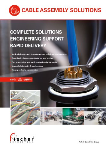
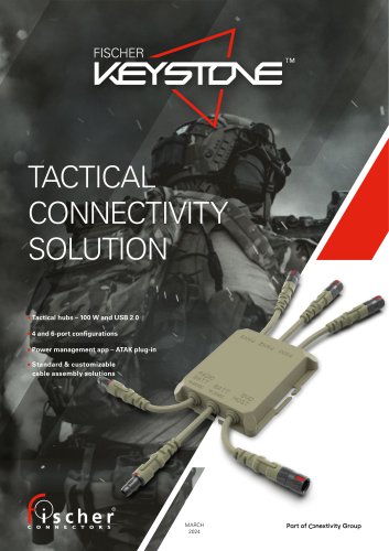
Fischer Connectors offers integrated connectivity solutions, including rugged and submersible cable assemblies.
Custom overmolding options are available for various series, providing solutions for specific applications.
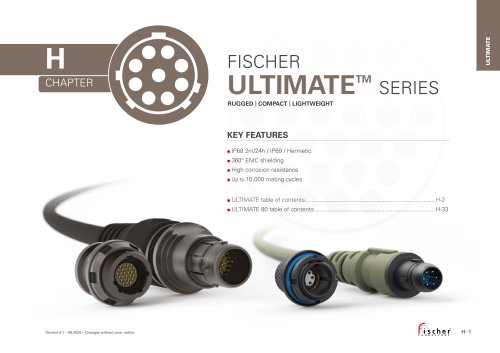
The Fischer Ultimate Series features rugged, compact, and lightweight connectors with high corrosion resistance and up to 10,000 mating cycles.
Connectors meet IP68/IP69 standards, capable of withstanding 2 meters of submersion for 24 hours.
Operating temperature range is from -55°C to +135°C, with corrosion resistance tested with a 1,000-hour salt mist exposure.
Connectors can endure 10,000 mating cycles, with specific conditions for pin layout 204H.
Connectors can withstand a 300g amplitude shock with a half sine pulse of 3 ms.
Contact resistance varies by contact size, with insulation resistance greater than 1010 Ω.
Connectors support various data transmission standards, including USB 2.0, USB 3.2, Ethernet, and Audio/Video.
Details on various body styles and technical dimensions for plugs and receptacles are provided.
Accessories include sealing caps and tooling options for assembly and maintenance.
1. General Specifications: Detailed technical specifications for Fischer UltiMate 80 connectors and Fischer FiberOptic Series.
2. Environmental & Mechanical Data: Sealing performance: IP68, operating temperature range: -55°C to +135°C, corrosion resistance: 500 hours in salt mist conditions.
3. Electrical Data: Contact and shell resistance: <10 mΩ, insulation resistance: >1010 Ω.
4. Material & Surface Finish: Housing and nut made from aluminum with black nickel finish.
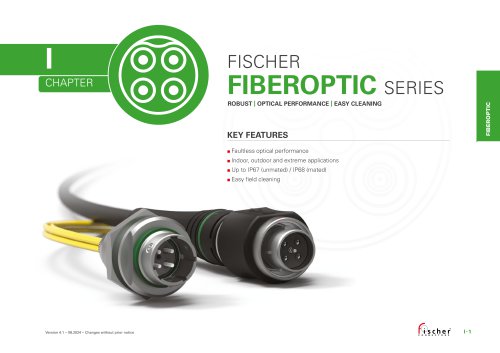
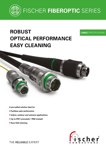
5. Fischer FiberOptic Series: Designed for robust optical performance.
6. Configuration and Accessories: Detailed configuration matrix for plugs and receptacles.
7. Technical Dimensions: All dimensions are provided in millimeters.
The document provides technical specifications for Fischer Connectors' MiniMax and Freedom series connectors.
Materials include hardened tool steel, nickel-plated brass, stainless steel, and plastic. Sealing performance: IP68 water sealing and gas sealing capabilities.
Cable assembly requires special tooling developed by Fischer Connectors.
360° mating freedom, non-magnetic quick-release locking mechanism, membrane-sealed contacts.
Detailed dimensions for various connector sizes and configurations.
Contact resistance is typically 5 mΩ, with insulation resistance greater than 1010 Ω.
Includes standards for sealing, temperature, corrosion, endurance, vibration, and shock resistance.
The document provides comprehensive technical details for Fischer Connectors' MiniMax and Freedom series, highlighting their robust design and performance standards.
Catalog excerpts
TECHNICAL SPECIFICATIONS VOLUME 2 ULTIMATE FIBEROPTIC MINIMAX FREEDOM
Open the catalog to page 1
TABLE OF CONTENTS GENERAL INFORMATION FISCHER FIBEROPTIC SERIES
Open the catalog to page 2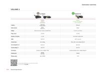
Connector overview OPTICAL PERFORMANCE EASY CLEANING Push-pull Quick-release Brass Aluminum Nickel Anthracite / Black (ULTIMATE 80) Chrome over Nickel Fiber optic / Low voltage (hybrid) Contact: Crimp / Solder / PCB Contact: Optical termini / Solder (hybrid) Sealing level Mating cycles Locking Shell material Plating Technical specifications for our Fischer Core Series can be found in VOLUME 1. Technical Specifications
Open the catalog to page 3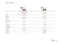
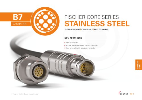
Connector overview HIGH-DENSITY MINIATURIZATION EASY MATING HIGH-SPEED DATA TRANSFER EASY CLEANING EASY INTEGRATION Push-pull Screw-locking / Quick-release Brass Stainless Steel 316L Chrome over Nickel Anthracite Nickel Anthracite Nickel Contact: Solder / PCB / Wires / ZIF Sealing level Mating cycles Locking Shell material Plating Plug ø [mm] Number of contacts AWG Contact type
Open the catalog to page 4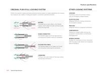
Product specifications ORIGINAL PUSH-PULL LOCKING SYSTEM OTHER LOCKING SYSTEMS Fischer Connectors’ original push-pull automatic locking system is widely adopted by the industry for its ease of use, safety of mating and speed in connection and disconnection. LANYARD Combines push-pull automatic locking with an emergency release lanyard. outer sleeve Receptacle Receptacle flexible fingers Receptacle Receptacle outer sleeve outer outer sleeve sleeve Plug Plug flexible fingers plug body flexible flexible fingers fingers groove groove MATING The plug has an outer sleeve, with flexible fingers, which...
Open the catalog to page 5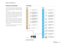
Product specifications SEALING CATEGORIES The IP (Ingress Protection) classification system provides a reliable method of comparing relative levels of sealing between various connector products. The protection level offered by a typical envelope is described in IEC 60529, published by the International Electrotechnical Commission (IEC). While the first number describes the level of protection from solid objects, the second one relates to protection from liquids. The digits indicate conformity with the conditions summarized in the tables aside. Protected against solid objects greater than 50 mm...
Open the catalog to page 6
Product specifications O-rings COMMONLY USED SEALING LEVELS IP50 indoor unexposed applications IP68 watertight sealing Hermetic sealing Each requires different sealing levels and, therefore, different connector solutions. IP50 INDOOR / UNEXPOSED APPLICATIONS Typically for indoor or industrial applications, the required sealing level is IP50, since the device needs to be protected against dust but not exposed to water. The IP50 rating can be improved with additional accessories like boots or protective sleeves. IP68 WATERTIGHT SEALING Typically for applications requiring outdoor use where they...
Open the catalog to page 7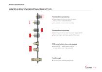
Product specifications HOW TO CHOOSE YOUR RECEPTACLE BODY STYLES Front and rear projecting Depending on whether you need the space saving inside or outside the device Also available in front or rear mounting Front and rear mounting Depending on how you need to process your assembly Rear mounting is commonly used for PCB mount SEALING MATERIAL IP68 watertight or hermetic designs Hermetic has a specific sealing material for best sealing under high pressures Feedthrough Hermetic panel bulkhead feedthrough
Open the catalog to page 8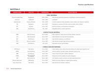
Product specifications MATERIALS MATERIAL NAME MAIN ATTRIBUTES SHELL MATERIAL Chromium-plated brass Salt mist and mechanical resistance, cost efficiency, electrical conductivity Stainless steel Cleaning / Radiation Corrosion resistance, surface cleanability, nuclear radiation and mechanical resistance Sterilization in autoclave, EtO, Cidex, gamma radiation, Steris®, Sterrad® Electrical insulation, low temperature manipulation Cost efficiency Disposable solutions, medical applications CONTACT BLOCK MATERIAL PEEK High temperature High temperature, high chemical and high radiation resistance High...
Open the catalog to page 9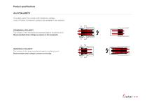
Product specifications A/Z POLARITY To protect users from contact with dangerous voltage, most of Fischer Connectors’ products are available in two versions : STANDARD A POLARITY The contacts of the receptacle are protected against accidental touch. Recommended when voltage is present on the receptacle. INVERTED Z POLARITY The contacts of the plug are protected against accidental touch. Recommended when voltage is present on the plug.
Open the catalog to page 10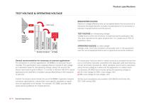
Product specifications TEST VOLTAGE & OPERATING VOLTAGE Operating voltage Operating voltage Creepage distance & airgap Test voltage Typical scatter of breakdown voltage values Breakdown voltage BREAKDOWN VOLTAGE Maximum voltage difference that can be applied before the occurrence of a disruptive discharge between mutually insulated portions of a connector or between insulated portions and the ground. TEST VOLTAGE (or withstanding voltage) Voltage level at which the connector is tested during the qualification test. This value represents the upper physical limit. It is usually set at 75% of breakdown...
Open the catalog to page 11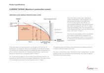
Product specifications CURRENT RATING (Maximum permissible current) DERATING CURVE DERIVED FROM THE BASIC CURVE Current l Upper temperature limit Upper current limit (wires, cable) (Derated) Operating area Basic curve The current values listed under “Electrical & contact configurations” were measured in our test laboratory according to IEC 60512-5-2: Current-carrying capacity test, Test 5b: Current-temperature derating. They are the currents that create a temperature rise of 40 °C (unless otherwise specified) within the connectors due to the self-generated heat, and they belong to the basic curve...
Open the catalog to page 12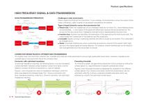
Product specifications HIGH FREQUENCY SIGNAL & DATA TRANSMISSION INPUT Challenges in data transmission When a signal is emitted at the transmitter, it must undergo minimal distortion across the system (transmitter, connectors, cable, receiver) to be properly recovered at the receiver. DATA TRANSMISSION PRINCIPLES Types of signal distortion across the transmission link: Return loss: When the impedances of two interfaced media do not match (i.e., transmitter/connector, connector/cable, ...), some parts of the signal will reflect back towards the source and be lost. The amount of this loss comes...
Open the catalog to page 13All Fischer Connectors catalogs and technical brochures
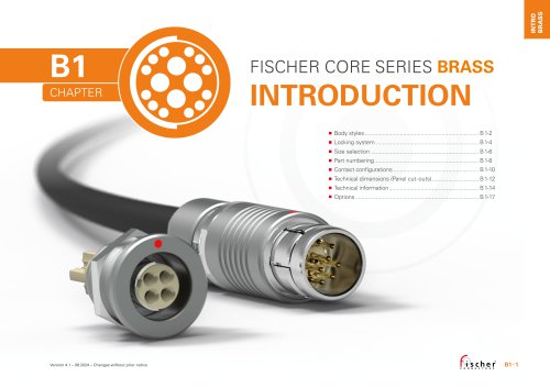 Fischer Core Series Brass
178 Pages
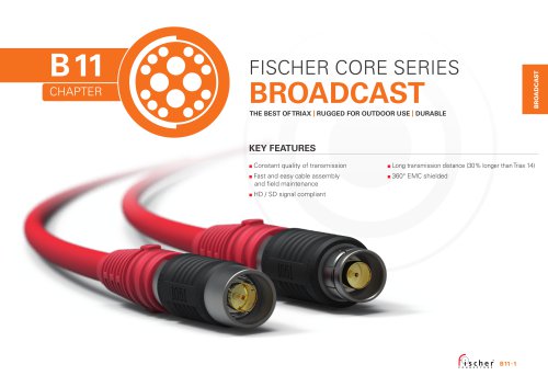 Fischer Core Series Broadcast
29 Pages
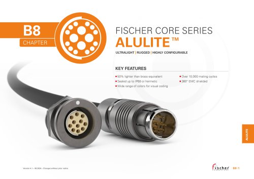 Fischer Core Series Alulite™
32 Pages
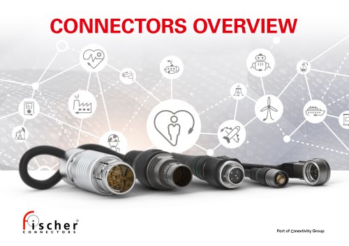 Connectors Overview
2 Pages
 Cable Assembly Solutions
4 Pages
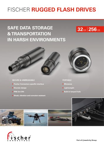 Fischer Rugged Flash Drives
4 Pages
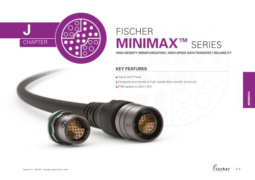 Fischer MiniMax™ Series
27 Pages
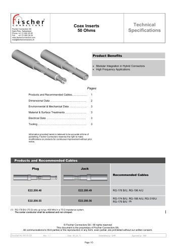 Coax Inserts 50 Ohms
3 Pages
 Fischer FiberOptic Series
32 Pages
 Fischer UltiMate™ Series
45 Pages
 Technical Specifications Volume 1
293 Pages
- Aircraft connector
- Data connector
- Board connector
- Round connector
- Circular connector
- Electrical power supply connector
- MiL connector
- High-density connector
- High-speed connector
- Miniature connector
- Modular connector
- Waterproof connector
- Compact connector
- Custom connector
- Fiber optics connector
- Push-pull connector
- Hybrid connector
- High-performance connector