- Catalogs
- FAULHABER Drive Systems
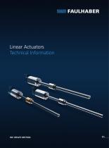
- Linear actuators L series
- Company
- Products
- Catalogs
- News & Trends
- Exhibitions
Linear actuators L series

Linear actuators L series
The FAULHABER Linear Actuator L series is engineered for high performance in compact dimensions, ideal for robotics, industrial machines, and laboratory equipment. It offers various reduction ratios and screw configurations to accommodate different force and speed needs, with flexibility for diverse ambient conditions and mechanical integration.
Service Life
The operational lifetime is influenced by factors such as screw and nut type, axial load, motor temperature, and operating conditions, making precise lifetime prediction challenging.
Screw Types
The series includes lead and ball screws, each with unique characteristics. Ball screws offer high efficiency due to rolling movement, while lead screws may be preferable for specific applications.
Motor Combinations
The actuators can be paired with various DC, brushless, and stepper motors, optimized for torque and speed.
Modifications and Options
A variety of standard options and modifications are available to meet specific application needs, including screw and nut types, ambient conditions, and motor integration.
Technical Specifications
Detailed specifications include reduction ratios, output speeds, axial forces, and efficiencies, along with material selections and operating temperature ranges.
Performance Parameters
Key performance parameters include continuous and peak output speeds, axial forces, and efficiencies. Adhering to recommended values is crucial for optimal performance and longevity.
Material and Construction
The actuators are constructed with stainless steel for screws, nuts, and housing, ensuring durability and resistance to various conditions.
Critical Speed and Buckling
The document discusses critical speed and buckling forces, providing guidelines for safe operation within specified limits.
Overview
This document provides technical information on linear actuators, focusing on critical speed, buckling force, and selection criteria for optimal performance. It includes formulas for calculating critical speed and buckling force, guidelines for selecting linear actuators, and considerations for motor selection.
Critical Speed
The critical speed of a screw depends on its geometry and support method, calculated using the formula: ncr = k · 106 · (dr / l2max) · S. The critical speed should not be reached during operation to avoid system damage.
Buckling Force
The maximal compressive force a screw can withstand before buckling is calculated using: Fb = kb · (dr)4 / l2max · S · 103. Ensuring the buckling force exceeds the maximum cycle force is crucial to prevent deformation.
Linear Actuator Selection
The selection process involves evaluating mechanical requirements, linear speed, axial force, and power. Key steps include:
- Mechanical Requirements: Filter products based on screw type and available space.
- Linear Speed: Ensure the critical speed and peak output speed exceed the required speeds.
- Axial Force: Verify that buckling and peak axial forces are above required forces.
- Power: Check that the actuator can deliver the necessary mechanical power.
Motor Selection
Calculate input rotational speed and torque using provided formulas. Consider factors like system inertia, movement direction, and motor temperature to ensure optimal performance and longevity.
Design and Components
The document outlines the basic design of linear actuators, including components like motor flange, coupler housing, planetary gear train, and ball bearings.
Additional Information
The document emphasizes the importance of consulting Faulhaber's online tools and sales engineers for tailored solutions, considering specific application requirements and constraints.
Catalog excerpts
Linear Actuators Technical Information
Open the catalog to page 1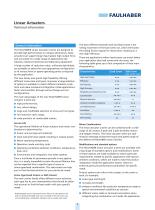
Linear Actuators Technical information The basic different between ball and lead screws is the rolling movement of the ball screw nut, which eliminates the sliding friction typical for lead screws, resulting in a very high efficiency. General information The FAULHABER Linear Actuator L series are designed to provide high performances in compact dimensions, these actuators can support large input speed, high output force and are suited for a wide range of applications like robotics, industrial machines and laboratory equipment. There are applications where lead screws can match better your application...
Open the catalog to page 2
Linear Actuators Technical information Note that most options are modifying the basic product so that characteristics will differ from the performance of the standard version. This latest aspect should be considered when selecting an option and eventual questions should be addressed to your local sales representative. Linear Actuators Gearhead with integrated Ball Screw Series 22L ... SB Values at 22°C Number of gear stages Reduction ratio 1) (rounded) Notes on technical datasheet Unspecified tolerances mm/s 120 100…45,4 Continuous output speed, max. 2) If not specified, speed, max.2) in accordance...
Open the catalog to page 3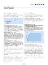
Linear Actuators Technical information Peak output speed, max vp max [mm/s] Designates the maximum permissible peak linear speed. This results from the product of the maximum permissible rotational peak speed and the screw lead. Output Power max. Pout max [N] Designates the maximum recommended output power during operation. This level should not be exceeded in any operation phase to obtain optimum life performance. Efficiency of gearhead/coupler, max. ηg max [%] The maximum efficiency refers to the continuous operation mode. Such value varies depending on the number of stages and could also depend...
Open the catalog to page 4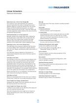
Linear Actuators Technical information Mass [g] The average mass of the linear actuator including standard length screw. Radial load, max. (15 mm from flange) [N] The maximum screw load represents the maximum dynamic load (when the screw is rotating) that can be applied radially at a particular distance from the output flange and that the ball bearing system can support without impacting the service life. In case the radial load would be applied at another distance this value should be extrapolated appropriately. Screw type I Diameter (Ø) [mm] Nominal diameter used for designation. I Lead p [mm]...
Open the catalog to page 5
Linear Actuators Technical information Critical Speed [mm/s] The critical speed is reached when the rotational frequency of the screw equals its first natural frequency, thus causing resonant vibrations. Buckling Force [N] When subject to an axial compressive force, the screw can permanently deform and eventually break (buckling). The maximal compressive force depends on the screw geometry and support method according to the formula below. The critical speed depends on screw geometry and support method according to the formula below, a safety factor is also considered to take into account other...
Open the catalog to page 6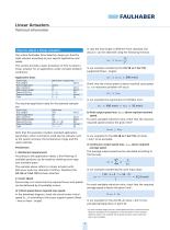
Linear Actuators Technical information In case the hub length is different from standard, the actual vcr can be obtained using the following formula: How to select a linear actuator Our online Faulhaber Drive Selection helps you find the right solution according to your specific application and needs. This section provides a basic procedure of how to select a linear actuator for an application under constant ambient conditions. In our example considering the 22L SB xx:1 6x2 150, supported (fixed – single): Application Data: Screw Type Hub Length Screw Supported Max. Diameter Max. Drive Length...
Open the catalog to page 7
Linear Actuators Technical information 3. Axial Force Next step is to check if the remaining linear actuator configurations can support the required forces. In our example considering the cycle input data: 3 a) Buckling force above required max force. In the datasheet diagram check the actual screw buckling force (Fb_std) according to the screw support system (fixed – free or fixed – single). In case the hub length is different from standard calculate the actual Fb according to the formula: In our example the requirement is satisfied for all ratios. Note that it is possible to operate the linear...
Open the catalog to page 8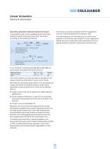
Linear Actuators Technical information The results can also be compared with the suggestions from our online Faulhaber Drive Selection Tool. Input Data calculation: Rotational Speed and Torque To proceed for each of the available solution the input rotational speed and torque have to be calculated, according to the following formulas: Our sales engineers can also help you to confirm your selection or to find the right solution for your application taking into account also particular requirements such as special ambient conditions, mechanical constraints, etc. Fj · p · 100 100 Min_ j = __________...
Open the catalog to page 9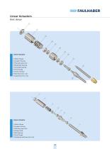
Linear Actuators Basic design 1 Motor Flange Coupler Housing Planetary gear train Radial ball bearings Axial ball bearings Front Flange Screw interface Ball Screw (incl. nut) Lead Screw (incl. nut) Motor Flange Coupler Housing Planetary gear train Output shaft Ball bearings Front Flange Standard Lead Screw (incl. nut)
Open the catalog to page 10
More information faulhaber.com faulhaber.com/facebook faulhaber.com/youtubeEN faulhaber.com/linkedin faulhaber.com/instagram All rights reserved, including translation rights. No part of this description may be duplicated, reproduced, stored in an information system or processed or transferred in any other form without prior express written permission of Dr. Fritz Faulhaber GmbH & Co. KG. This document has been prepared with care. Dr. Fritz Faulhaber GmbH & Co. KG cannot accept any liability for any errors in this document or for the consequences of such errors. Equally, no liability can be accepted...
Open the catalog to page 12All FAULHABER Drive Systems catalogs and technical brochures
 MC 3603 S
2 Pages
 Series 0620 ... B
2 Pages
 Series 0308 ... B
2 Pages
 Series 0816 ... SR
2 Pages
 Series 2232 ... SR
2 Pages
 Series 0615 ... S
2 Pages
 Technical Information
160 Pages
 Series 3242 ... BX4
2 Pages
 1224_SR
2 Pages
 1219_G
2 Pages
 1024_SR
2 Pages
 1016_SR
2 Pages
 1512 ... SR
1 Page
 1506 ... SR
2 Pages
Archived catalogs
 MCDC 3006 S
2 Pages
 1319_SR
2 Pages
 Drive systems 2020 - 2021
656 Pages
 Faulhaber motion 02/2021
28 Pages
 FAULHABER motion 1/2022
33 Pages


- Aircraft actuator
- Electric actuator
- Synchronous electric motor
- Light aircraft electric motor
- Brushless electric motor
- Motor controller
- Aircraft motor controller
- DC motor controller
- Brushless motor controller
- Screw actuator
- Compact actuator
- Stepper actuator
- Encoder
- Aircraft encoder
- Pneumatic actuator
- Incremental encoder