AUDITCON® 2 SERIES LOCKS

AUDITCON® 2 SERIES LOCKS
These instructions provide a detailed guide for installing the Auditcon 2 Series Locks, specifically models 52, T52, 252, and 552 with vertical housing dead bolts. The document outlines the necessary steps and precautions to ensure proper installation and maintain security agency approvals.
1. Use the provided template to mark the mounting holes for the dial and lock assemblies.
2. Ensure the spindle hole diameter is between 10.3mm and 11.1mm, with 10.3mm recommended.
3. Drill and tap holes for the dial assembly screws to a depth of 9.5mm if possible.
4. Ensure the lock bolt moves freely and only in the axial direction.
5. Connect additional boltwork parts using screws with a maximum torque of 200Ncm.
1. Insert a cable shield into the spindle hole.
2. Place the protective tube over the lock case's tube retainer.
3. Guide the tube through the spindle hole and mark it flush to the door.
4. Cut the tube and mount the lock case assembly using specified screws and torque.
5. Insert the spindle and align it with the drive cam grooves.
- Bolt dimensions: 8 x 25.4mm
- Bolt movement and extension: 11.8mm
- Maximum load movable by the bolt: 22N
- Maximum load against bolt when thrown: 1kN
- Suitable for safes or vault doors of any material.
1. Remove the front cover from the keypad/base assembly.
2. Guide the ribbon cable through the keypad/base assembly.
3. Attach the keypad/base assembly to the door.
4. Connect the ribbon cable to the keypad.
5. Fold excess cable and secure the front cover.
1. Test lock operation by entering the factory combination.
2. Tighten all screws and apply lubricant to the gear and dial.
3. Install the spindle mounting clip and apply the tamper-evident dial label.
4. If applicable, install a 9V battery for the Battery Assist option.
- Do not disassemble the lock case assembly.
- Use an ESD wrist band during installation to prevent electrostatic discharge damage.
- Follow all instructions to maintain security approvals.
For technical support, contact dormakaba USA Inc. at (800) 950-4744.
Catalog excerpts

AUDITCON® 2 SERIES LOCKS MODELS 52, T52, 252, 552 - VERTICAL HOUSING DEAD BOLT INSTALLATION INSTRUCTIONS Front Cover & Keypad Assembly Lock Case Assembly Cable Shields (2) Front Cover Mounting Screws (3) Dial Label Keypad/Base Mounting Screws (2) Spindle Clip Design Parameters for Auditcon 2 Series Locks Lock Case Mounting Screws (4) 1. Bolt dimensions (nominal): .312 inches x 1.000 inches/ 3. olt extension: .465 inches/11.8 mm B 4. Maximum load movable by the bolt: 5 lbs. (22N) NOTE: Auditcon 2 dead bolt locks may not open if more than 5 lbs. (22N) of force is applied to the end or side of the bolt. Spindle & Tube The installation instructions are the basis for Security Agency Approvals. The lock installation must be done in accordance to these instructions in order to maintain the labeled approval level. Spindle Mounting Not Shown in Photo: Insulator Tape Screw Figure 1 - Dead Bolt Lock Parts 5. Maximum load against bolt when thrown (all directions): 224.8 lbs. (1kN) 6. he lock can be fitted to safes or vault doors of any T material. NOTE: As is the case with all mechanical and electronic locking devices, the container and boltworks must be designed to protect the lock. Basic Tools and Materials Needed • edium Phillips head screwdriver (#2) (recommend M magnetized tip) • ine pitch hacksaw (32 teeth/inch) F • Small flat file • All-purpose scissors • Tape measure or ruler • ESD wrist band • orque screwdriver (30 inch-pounds/3.4 newton-meters T capacity) • Small vise grip • Needle-nosed pliers • Loctite® 262 (Red) for use on lock case mounting screws Prepare for New Installation of the Lock (If Required) 1. Use the installation template provided to establish the exact locations (relative to the spindle hole) of the mounting holes for the dial assembly and the lock assembly. 2. The spindle hole diameter can be a minimum of .406” (10.3mm) to a maximum of .438” (11.1mm). The .406” (10.3mm) diameter is recommended. Spindle hole must be deburred. 3. he dial assembly mounting screws require drilled and T tapped holes to 3/8” (9.5mm) depth if possible (minimum 1/4” or 6.4mm depth required.) Drill either the two horizontal mounting holes or the two vertical holes. 4. When mounting the lock unit (i.e., integrating it in a boltwork), make sure that the lock bolt has clearance to freely move to its end positions and that the shifting force works only in the axial direction (direction of movement). Lateral forces should not be exerted on the lock. 5. If other parts of the boltwork are to be connected to the lock unit (e.g., for activating a blocking device), corresponding adapters can be fixed with screws (#10-32 or M4) to the front of the lock bolt (tightening torque for 15mm screwing depth: 200Ncm maximum). (P/N) 3045.025 Rev E 05/19 • © copyright 2005 - 2019 WARNING: dormakaba locks are protected from 25,000 V Electrostatic Discharge (ESD) damage when correctly installed. Follow these precautions to avoid ESD damage when installing the lock: • Handle the keypad assembly by the outer edge only. • se an ESD wrist band grounded to the lock or container U during installation. Part I: Install Lock Case Assembly WARNING: Do not take the lock case assembly apart. There are no field servicable parts inside lock case. This action will void the warranty. 1. Insert a cable shield into the Figure 2 deburred spindle hole from the back side of the container door. 2. Place the protective tube over the tube retainer on the lock case. (Figure 2) 3. hile holding the lock case W assembly, guide the tube through the spindle hole and place the lock case flush against the inside of the container door. 4. Mark the tube flush to the outside of the container door (to within 1/16” or 1.6mm). 5. Remove lock case assembly from door and cut the tube just inside your
Open the catalog to page 1
6. lug one end of the ribbon cable into the connector on the bottom of the lock case. (Figure 3) P 7. ay the ribbon cable in the cable routing path on the lock case and tape the cable to the outside L of the tube with the insulator tape provided. (Figure 3) 8. old the lock case assembly and carefully guide the loose end of the ribbon cable and the tube H through the spindle hole so that they are accessible outside of the container door. 9. Mount the lock case assembly to the inside of the container door using the four 1/4-20 (or M6-1) lock case mounting screws. (Torque 25-30 lbs., 2.8-3.4 N-M)...
Open the catalog to page 2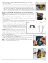
13. Test the operation of the lock before completing the installation of the front cover by verifying the following: • nsure that the dial turns freely without scraping. If necessary, re-adjust the keypad/base E assembly mounting screws, the position of the spindle, or replace the spindle completely. • ower the lock by turning the dial briskly in any direction until simultaneous green and P red flashes display and two beeps sound to indicate the lock is powered. Position the lock dial to the HOME position and key in the Factory Combination. (For a Model 52 or T52, enter “502550”. For a Model...
Open the catalog to page 3
www.dormakaba.us © 2005-2019 dormakaba USA Inc. All rights reserved. Product warranty information can be found at: www.dormakaba.us NOTICE: The information in this instruction sheet is subject to change without notice and does not represent a commitment on the part of dormakaba. dormakaba shall not be liable for technical or editorial errors or omissions contained herein; nor for incidental or consequential damages resulting from the furnishing, performance or use of this material. dormakaba USA Inc. 749 W. Short Street, Lexington, KY 40508 USA Phone: (859) 253-4744 FAX: (859) 255-2655 Technical...
Open the catalog to page 4All Dormakaba catalogs and technical brochures
 Charon
12 Pages
 Kerberos
16 Pages
 Kentaur
20 Pages
 KTC 3/KTC 4
12 Pages
 KTC 2
KTC 211 Pages
 Geryon
24 Pages
 pextra Q
16 Pages
 penta
penta16 Pages
 ST PRO Green RC2 / RC3
28 Pages
 Argus 40-60-80 Argus V60
52 Pages
 Orthos PIL-M02
12 Pages
 Orthos
20 Pages
 Sensor Barrier Argus 40
2 Pages
 Argus Air Boarding
2 Pages
 Kaba EACM
24 Pages
 Airport solution catalogue
16 Pages


Archived catalogs
 KTV 3 KTV 4 KTV ATRIUM
28 Pages
 lodging-brochure
12 Pages
 dormakaba c-lever pro
2 Pages
 Push Butoon Lock Brochure
16 Pages
 dormakaba Overview Brochure
17 Pages
 Padlock and Enclosure Lock
16 Pages
 dormakaba digital cylinder
2 Pages
 whichdoorcontrolbrochure
7 Pages
 RTS 85
8 Pages
 Kaba smart key
2 Pages
 dormakaba c-lever compact
2 Pages
 cyber-security
8 Pages
 Charon Turnstiles
12 Pages
 hsb-and-hsg
16 Pages
 Kaba 20
2 Pages
 OFFICE Mundus
2 Pages
 2019 Orthos Personal Interlocks
20 Pages
 B-eco
B-eco2 Pages
 Combi B 30
4 Pages
 SST FLEX
12 Pages
 Kaba exos 9300
2 Pages
 Kaba exos 9300 Basic system
2 Pages
 airport-solutions
24 Pages
 Orthos Personal Interlocks
24 Pages


- KENNAMETAL airport software
- Maintenance software
- KENNAMETAL fingerprint reader
- KENNAMETAL biometric fingerprint reader
- KENNAMETAL optical fingerprint reader
- Airport turnstile
- Airport lock
- Mechanical lock
- High security lock
- Boarding e-gate
- Airport self-boarding gate
- Airport revolving door
- Standalone fingerprint reader
- Electronic lock
- Access control card reader
- Airport card reader
- Airport fingerprint reader
- Card fingerprint reader
- Airport security air lock