- Catalogs
- DELAIR-TECH
- White-paper
White-paper

White-paper
The document discusses the advantages of using a precision GNSS/IMU system to enhance the accuracy of photogrammetric products such as DSM, DTM, orthophotography, stereoscopic restitution, and 3D models. The primary benefit is reducing or eliminating the need for ground-based reference points.
Vector and Payload
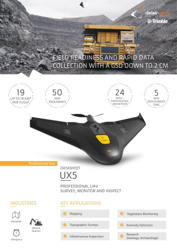
The DT26X drone was used, featuring a 2.5-hour endurance, 3.3 m wingspan, and a payload capacity of up to 4 kg. The payload included a Sony Alpha 7 R camera with a 35 mm lens, providing high-quality images with a ground coverage of 103 x 105 m at 150 m altitude.
Calibration Field
A test zone of 300 x 350 m was selected, with 15 control points measured using a Trimble R10 for accuracy. This setup ensured precise validation of results.
Operation Mode
A cross-flight at two heights was conducted to resolve ambiguities related to camera and GNSS/IMU setup. The flight paths were designed to maximize image overlap and autocorrelation points.
Acquisition
The flight on 5 June 2015 faced challenging wind and turbulence conditions but was completed successfully, maintaining an 80% image overlap.
Aerotriangulation
Post-processing of navigation data was done using POSPac software. The initial results showed satisfactory precision for direct georeferencing. Further adjustments using control points improved accuracy to about 3 cm in planimetry and 6 cm in altimetry.
Conclusion
The study demonstrates that high precision can be achieved without control points, with further improvements possible by using a small number of control points. The GNSS/IMU solution is integrated into the DT18 drone, with plans for further testing to confirm these findings.
Catalog excerpts

/ delsir tech White paper^ __ Jean Francois Aumont (1), Bastien Mancini (2). (1) Image processing manager, Delair-Tech, (2) Managing director, Delair-Tech. Jean Frangois Aumont Bastien Mancini
Open the catalog to page 1
Introduction Vector and Payload Calibration field Operation Mode Aerotriangulation Conlusion 2 Auteurs: Jean François Aumont / Bastien Mancini
Open the catalog to page 2
The purpose of this document is to show the Let us examine the following case study, that we benefit of a precision GNSS/IMU on the accuracy carried out in June 2015. of products obtained by photogrammetry (DSM, DTM, orthophotography, stereoscopic restitution, 3D model). The benefit of this precision GNSS/IMU combination will be to minimise or eliminate the need for work on the ground such as the establishment of a reference base and/or control points. 3 Auteurs: Jean François Aumont / Bastien Mancini
Open the catalog to page 3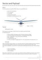
Vector and Payload Vector For this acquisition, we used the DT26X, whose main specifications are: ◊ ◊ ◊ ◊ ◊ Up to 2.5 h of endurance 3.3 m wingspan 1.6 m length 50 km/h cruising speed Possibility of carrying loads up to 4 kg Payload Photographic sensor This consists of a Sony Alpha 7 R and a Sony 35 mm fixed lens (Ref: SEL35F28Z). Its characteristics are: ◊ ◊ ◊ ◊ ◊ ◊ Sensor installed in landscape mode in the drone’s direction of flight 4.9 microns (physical size of the pixels), ensuring good image quality 4912 x 7360 pixels, i.e. a 24 x 36 mm sensor (full format) Fixed, stable lens 1 s maximum...
Open the catalog to page 4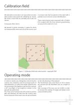
Calibration field We selected our test zone in an area where we were 4 surveyor nails that we placed on the road (with a able to place many points for validating our results. painted cross to ensure correct identification). We chose a zone that we normally use to test our drones. These control points were measured with a Trimble R10 coupled with the Teria network guaranteeing It measures 300 x 350 m. accuracy to the order of 2-3 cm. We placed 15 points, including 11 plates for which we measured the centre and one of the corners, and Figure 2 - Calibration field and control points - copyright...
Open the catalog to page 5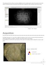
The photogrammetry software used was UASMaster, which enables good control of tie points and control points. The data were also processed with PIX4D and Correlator3D, with consistent and similar results. Acquisition The flight took place on 5 June 2015 in difficult conditions, both in terms of wind and thermal turbulence. Despite these difficult conditions, the flight went ahead without any problem. It was difficult to maintain the axis because of the wind, but overlaps of 80% enabled the study to take place. Figure 4 - Calibration field control points center of images acquired 6 Auteurs: Jean...
Open the catalog to page 6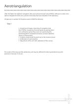
Aerotriangulation After the flight, the Applanix navigation data were post-processed using POSPac software in order to be able to integrate the lever arms, and the time delay that was evaluated in the laboratory. All data are in Lambert-93 Projection and in IGN69 for altimetry. Step 1 ◊ Importing of images, importing of navigation data from POSPac, importing of control points by putting them into verification points (they were not used during the aerotriangulation calculations however we have statistical values on these points). ◊ Creation of automatic tie points up to the maximum level. ◊ Verification...
Open the catalog to page 7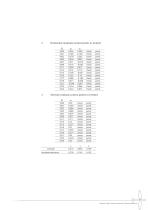
0 Horizontal residuals control points in [meter] 0 Vertical residuals control points in [meter] Auteurs: Jean Frangois Aumont/ Bastien Mancini
Open the catalog to page 8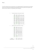
To see the contribution of the control points on our calibration field, five control points (four at the edges and one in the centre) were activated for further adjustment of the unit and here is the excellent result (with an accuracy of about 3 cm in planimetry and 6 in altimetry). Horizontal residuals control points in [meter] Vertical redisuals control points in [meter] 9 Auteurs: Jean François Aumont / Bastien Manci
Open the catalog to page 9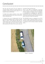
Conclusion We have seen here that if you are seeking an accurate solution without any control points, it is possible to obtain precision of the order of 15 cm by performing a suitable flight. acquisition of the site afterwards. Once in the office, all ambiguities concerning camera settings or angles between the GNSS/IMU and the camera are resolved, and the navigation is recalculated by integrating the parameters To obtain even greater precision, a few control observed from the “mini” calibration. In this case a points bring the precision down from the decimetre result with centimetre precision...
Open the catalog to page 10All DELAIR-TECH catalogs and technical brochures
 Delair UX11
2 Pages
 Sat bear
2 Pages
 Mama bear Antenna
2 Pages
 DT-Eye X
2 Pages
 DT-Eye
2 Pages
 DT-5Bands
2 Pages
 DT-4Bands
2 Pages
 DT-3Bands
2 Pages
 DT26X-PPK
2 Pages
 DT26X-Lidar
2 Pages
 DT18
DT182 Pages
 White-paper-DT18-PPK
15 Pages
 DT26X
DT26X2 Pages
 DT26M
DT26M2 Pages