- Catalogs
- DASSAULT SYSTEMES
- Virtual Modeling
Virtual Modeling

Virtual Modeling
Abstract
The packaging industry is undergoing significant changes with the integration of virtual modeling in the design and testing of plastic containers. This approach allows for the creation of commercially viable packages without the need for physical prototypes, focusing on improving performance characteristics such as drop impact resistance.
Introduction
Parker Plastics, a supplier of extrusion blow molded containers, faced issues with 1-gallon containers rupturing upon impact from a 3-foot drop. The study aimed to understand the failure reasons and improve the design to prevent such occurrences.
Analysis
Initial tests involved drop testing containers and mapping their thickness distribution using Abaqus/CAE. The simulation replicated the drop test conditions, showing stress and deformation patterns. The study identified that the container's parting line was a weak point, leading to ruptures.
Design Improvements
Modifications included altering the base corners and label panel area to reduce stress concentration. The new design showed a reduction in peak stress and strain, distributing stress over a wider area, thus improving impact performance.
Results
The new design significantly reduced impact failure rates. Further studies are exploring light-weighting the container while maintaining performance, using techniques like parison programming to redistribute material.
Conclusion
Virtual modeling facilitates the optimization of container designs, leading to lighter, more robust, and economical packaging solutions.
References
1. Coupled Fluid / Structure Interaction Simulation Using Abaqus CEL– General Motors, Simulia Customer Conference, 2010.
2. Abaqus for Package Development at Procter & Gamble – Henning, D. B., and Loudin, B. K., 2002.
Acknowledgment
PTI acknowledges Parker Plastics for their support and provision of container samples for testing and analysis.
Catalog excerpts
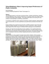
Virtual Modeling’s Role in Improving Impact Performance of Plastic Containers Sumit Mukherjee Predictive Modeling Department, Plastic Technologies, Inc. Abstract The packaging industry is on the brink of process change—including manufacturing, materials and their applications. New concepts are being born via computer screens and virtually nurtured to create commercially-viable packages. This is taking place before ever touching the mold, creating an actual package or conducting a physical test. It’s important to understand various aspects of processing, material properties, package design, product characteristics, as well as specifications and performance parameters that need to be met. Design guidelines have matured to the point where “moldable” geometry is part of the CAD software’s intelligent database. This helps take concepts, convert them to viable production ready designs and provide a degree of confidence that the package can be manufactured. However, the output from this stage does not tell us whether or not a specific performance characteristic—such as improving the drop impact performance—has been achieved. This is where the second component of virtual modeling comes into play. The intricate CAD geometry can be manipulated to add further definition regarding thickness and material properties. Introduction Parker Plastics is a major supplier of extrusion blow molded containers. These are plastic containers commonly molded from polyolefin materials such as high-density polyethylene and polypropylene. Extrusion blow molding is typically a manufacturing process of choice for handled containers like milk jugs, oil and detergent bottles. The process is desirable when a relatively large volume of liquid needs to handled by consumers in daily use such as pouring and filling. In one such scenario, it was observed that a significant proportion of the 1 Gallon, Figure 1: Rupture area on a drop tested 1 gal
Open the catalog to page 1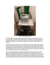
Figure 2: Drop test apparatus 230g filled bottles were encountering unacceptable rupture when dropped from a height of 3 feet. A filled gallon container typically weighs more than 4 kilograms and a height of 3 feet is a reasonable specification for a container that may slip out of consumer hands and impact the ground. The expectation is that the plastic container should not leak or explode under such conditions. This unexpected failure is shown in Figure 1 along the container’s view stripe region which also happens to be the mold parting line. This area is formed from multiple material flow fronts...
Open the catalog to page 2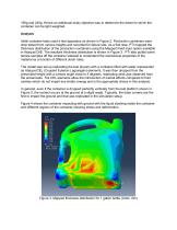
190g and 240g. Hence an additional study objective was to determine the extent to which the container can be light weighted. Analysis Initial container tests used a test apparatus as shown in Figure 2. Production containers were drop tested from various heights and recorded for failure rate. As a first step, PTI mapped the thickness distribution of the production containers using the Mapped Field input option available in Abaqus/CAE. The resultant thickness distribution is shown in Figure 3. PTI also pulled some tensile samples off the container sidewall to understand the mechanical properties...
Open the catalog to page 3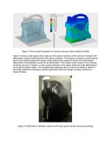
Figure 4. Drop impact simulation of a typical extrusion blow molded oil bottle Figure 5 shows a high speed video capture of the same container at the moment of impact with deformation closely matching that of the actual container. The physical container quickly retracts back to the original shape and unless a high speed video capture is made, the intermediate deformation characteristics would not be self-evident. The crease marks visible on the dropped container as seen in Figure 1 is also a good indicator of the region where the high deformations occur with possible rupture. The overall project...
Open the catalog to page 4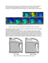
Figure 6 shows the container stress and deformation as the bottle bounces off the rigid floor with high stress regions propagating from the base corners to the upper sections of the container. As a consequence of the base deformation, the container bulges in the label panel Figure 6. Stress, strain and deformation of the 230g filled container upon impact with consequent regions of high strain along the parting line location where some of the tested containers were observed to rupture. The changes made to the design (as shown in Figure 7) alleviate the stress build up during impact by modifying...
Open the catalog to page 5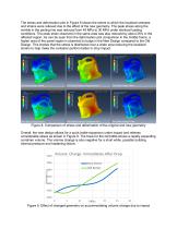
The stress and deformation plot in Figure 8 shows the extent to which the localized stresses and strains were relieved due to the effect of the new geometry. The peak stress along the wrinkle in the parting line was reduced from 45 MPa to 30 MPa under identical loading conditions. The peak strain observed in the same area was also reduced by about 25% in the affected region. As can be seen from the deformation plot comparison in the middle frame, a higher area of the panel region is observed to bulge in the New Design compared to the Old Design. This implies that the stress is distributed over...
Open the catalog to page 6
Parker Plastics prototyped the new design. Initial tests indicated that the impact failure problems from the 3 foot drop have been almost completely eliminated. Work is underway to investigate light weighting the container to 220g and 210g in steps. However, there are challenges with the lighter weight targets. Due to reduced thickness distribution, for the same impact energy, the force will distributed over a thinner cross sectional area causing the stresses to be higher. As long as the stresses are below the critical limit in the view stripe area, no failure is anticipated. A variety of techniques...
Open the catalog to page 7All DASSAULT SYSTEMES catalogs and technical brochures
 3DVIA home brochure
1 Page
Archived catalogs
 EXALEAD ONEPART REUSE
4 Pages
 MATRIX APPLIED COMPUTING
4 Pages
 EXALEAD ONECALL
4 Pages
- DASSAULT SYSTEMES aeronautic software
- DASSAULT SYSTEMES real-time software
- DASSAULT SYSTEMES process software
- DASSAULT SYSTEMES 3D software
- DASSAULT SYSTEMES cloud software
- Navigation software
- Test software
- Tracking software
- 2D software
- Web-based software
- DASSAULT SYSTEMES collaborative software
- CATIA V5 software