Catalog excerpts
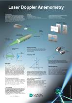
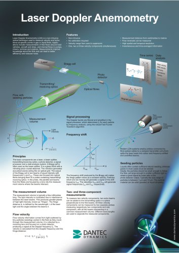
Principles The basic components are a laser, a beam splitter, transmitting/receiving optics, a photo detector, a signal processor and a data analysis system. A Bragg cell is often used as the beam splitter. It is a glass block with a vibrating piezo crystal attached. The vibration generates acoustical waves acting like an optical grid. The output of the Bragg cell is two beams of equal intensity with frequencies f0 and fshi(t. These are focused into optical fibres bringing them to a probe containing transmitting/ receiving optics. In the probe, the parallel exit beams from the fibres are focused by a lens into the measurement volume where the beams intersect. The measurement volume is typically a few millimetres long. The light intensity is modulated due to interference between the laser beams. This produces parallel planes of high light intensity, known as "fringes”. The fringe distance df is defined by the wavelength X of the laser light and the angle between the beams 0. Flow velocity information comes from light scattered by tiny particles (seeding) carried in the fluid as they move through the measurement volume. It is collected by a receiving lens and focused on a photo detector, producing a signal at the Doppler frequency fD. The velocity is calculated from the Doppler frequency and the fringe distance: The frequency shift produced by the Bragg cell makes the fringe pattern move at a constant velocity. Particles which are not moving will generate a signal of the shift frequency fshifl. The velocities Upos and Uneg will generate signal frequencies f™ and fneg, respectively. To measure two velocity components, two extra beams can be added to the transmitting optics in a plane perpendicular to the first beams. All three velocity components can be measured by two separate probes measuring respectively two components and one component, with all the beams intersecting in a common measurement volume. Different wave lengths are used to separate the measured components. Liquids often contain sufficient natural seeding, whereas gases in most cases must be seeded. Ideally, the particles should be small enough to follow the flow, yet large enough to scatter sufficient light to obtain a good signal-to-noise ratio at the photo detector output. Typically the size range of particles is between 1 pm and 10 pm. The ( material can be solid (powder) or liquid (d
Open the catalog to page 1All Dantec Dynamics catalogs and technical brochures
-
Shearography NDT
1 Pages
-
Particle Image Velocimetry
1 Pages

