- Catalogs
- Dantec Dynamics
- Digital Image Correlation for Deformation Measurement
Digital Image Correlation for Deformation Measurement
Digital Image Correlation for Deformation Measurement
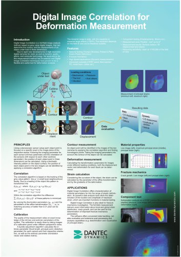
Digital Image Correlation (DIC) is a method for full-field image analysis that uses grey value digital images to determine the contour and displacements of an object under load in three dimensions. With advancements in high-resolution digital cameras and computer technology, DIC has become a versatile tool for deformation analysis, capable of measuring large strains (>100%) with scalable resolution depending on the field of view.
- Applications include material testing (e.g., Young’s Modulus, Poisson’s Ratio), fracture mechanics, high-speed applications, and advanced materials testing.
- Component testing for displacements and strains.
- Flexible measurement area ranging from millimeters to meters.
- Measurement results include surface contour, 3D displacement, and strains.
- High measuring sensitivity down to 1/100,000 of the field of view.
Correlation
Using a stereoscopic sensor setup, each object point is focused on a specific pixel in the image plane. The position of each object point in three dimensions is calculated using intrinsic and extrinsic parameters. A correlation algorithm tracks the grey value pattern in small local facets, minimizing the difference of these patterns to achieve high matching accuracy.
Calibration
Calibration involves taking images of a calibration panel from different perspectives. A bundle-adjustment algorithm calculates intrinsic parameters (focal length, principal point, distortion) and extrinsic parameters (translation vector, rotation matrix).
- Contour measurement: Identifying object points in images to calculate the object's contour.
- Deformation measurement: Determining displacement vectors and deformation for each facet under different loading conditions.
- Strain calculation: Calculating strain using affine transformation parameters and deformation gradients.
- Material characterization: Analyzing material parameters into the plastic deformation range and determining maximum strain locations.
- Fracture mechanics: Full-field measurement for local and global strain distribution and crack growth analysis.
- Mechanical
- Thermal
- Vibration
- Pressure
- Others
The software provides convenient data handling, reliable evaluation, and extensive post-processing capabilities, including the determination and visualization of principal strains.
Catalog excerpts

Digital Image Correlation for Deformation Measurement Introduction Digital Image Correlation is a full-field image analysis method, based on grey value digital images, that can determine the contour and the displacements of an object under load in three dimensions. Due to rapid new developments in high resolution digital cameras for static as well as dynamic applications, and computer technology, the applications for this measurement method has broadened and Digital Image Correlation techniques have proven to be a flexible and useful tool for deformation analysis. The dynamic range is wide, with the capability to measure large strains (>100%). The resolution depends on the field of view and is therefore scalable. Features • Material testing (Young’s Modulus, Poisson’s Ratio, Elasto-Plastic Behaviour) • Fracture mechanics • High Speed applications (Dynamic measurements) • Advanced materials (CFRP, wood, fibre injected PE, metal foam, rubber etc.) • Component testing (Displacements, Strains etc.) • Measurement area: Flexible - mm2 up to m2 • Measurement results: Surface contour, 3D displacement and strains • Measuring sensitivity: down to 1/100,000 of the field of view Loading conditions • Mechanical • Pressure • Thermal • And others • Vibration Object under test Measurement of principal strains (minimum left, maximum right). Resulting data Contour Data evaluation Displacement Contour measurement Material properties Using a stereoscopic sensor setup each object point is focused on a specific pixel in the image plane of the respective sensor. Knowing the imaging parameter for each sensor (intrinsic parameter) and the orientation of the sensors with respect to each other (extrinsic parameter), the position of each object point in three dimensions can be calculated. Using a stochastic intensity pattern on the object surface, the position of each object point in the two images can be identified by applying a correlation algorithm. An object point will be identified in the images of the two cameras by applying the correlation algorithm and finding homologous points. Taking the imaging parameters into account the contour of the object can be calculated. Live image (left), maximum principal strain (middle), principal strain (right). Strain calculation The correlation algorithm is based on the tracking of the grey value pattern G(x,y) in small local neighbourhood facets. Due to a loading of the object this pattern is transformed into Gt (xt ,yt ) where Gt (xt ,yt ) = g0 + g1 G(xt ,yt ) Considering the curvature of the object, the strain can be calculated by the parameter of the affine transformation and by the gradients of the deformation. Within the correlation algorithm the difference of these patterns is minimized. Calibration The quality of the measurement relies on exact knowledge of the intrinsic and extrinsic parameters of the system. The calibration is easily done by taking images of a calibration panel under different perspective views. A bundle-adjustment algorithm calculates the intrinsic parameter (focal length, principal point, distortion parameter) for each camera and their respective orientation, as well as the extrinsic parameter (translation vector and rotation matrix). Fracture mechanics Crack growth. Live image (left) and pricipal strain (right). APPLICATIONS Digital Image Correlation offers characterization of material parameters far into the range of plastic deformation. Its powerful data analysis tools allow the determination of the location and amplitude of maximum strain, which are important functions in material testing. Digital Image Correlation is also ideal for fracture mechanics investigation. The full-field measurement delivers exact information about local and global strain distribution, crack growth, and can be used for the determination of important fracture mechanics parameters. The software offers convenient data handling, reliable evaluation and extensive post-processing and analysis capabilities (e.g. determination and visualisation of principal strain). Component test Deformation analysis on a CFRP (carbon fibre reinforced plastics) structure. Live image (left) and out-of-plane deformation (right). Deformation measurement Calculating the transformation parameters for images under different loading conditions, both the displacement vector and deformation for each facet can be determined.
Open the catalog to page 1All Dantec Dynamics catalogs and technical brochures
 Shearography NDT
1 Page
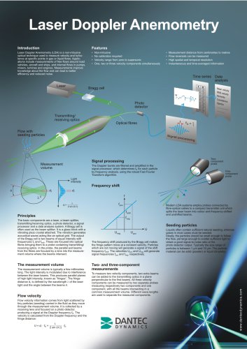 Laser Doppler Anemometry
1 Page