- Catalogs
- Cookson & Zinn
- Design Substantiation of PetroFast Modular Tank Unit
Design Substantiation of PetroFast Modular Tank Unit
Design Substantiation of PetroFast Modular Tank Unit
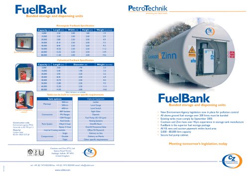
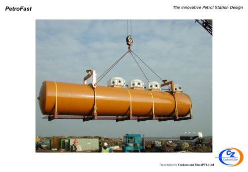
This document provides design verification for the PetroFast modular tank units with diameters of 1900, 2500, 2743, and 3000mm, available in single and double skin configurations. These tanks are part of a modular fuel dispensing unit range designed to simplify petrol station construction by integrating mounting points for canopy supports.
Design Challenge
The primary challenge is to streamline the design and manufacturing process to accelerate production and reduce costs. This involves adapting existing double-skin steel storage tanks to include canopy mounting points, adhering to European Standard EN12285-1:2018.
Design Considerations
The design considers the adequacy of pressure envelopes and canopy supports, assessed using finite element analysis (FEA) with Autodesk Inventor Nastran. Fatigue life is evaluated per BS.7608 standards. Design loads account for environmental conditions like snow, seismic, and wind loads, and potential vehicle collisions.
Load Cases
Four load cases are considered:
- Case 1 & 3: Downward loading with centrally located or single-sided canopy support.
- Case 2 & 4: Upward loading with centrally located or single-sided canopy support.
Materials and Construction
Materials conform to BS EN10025 S275JR standards. Multi-compartment tanks include internal dished heads for fuel separation, with stiffening rings as required by EN.12285-1:2018.
Concrete Canopy Anchor
The canopy loads are supported by a reinforced concrete slab, ensuring that moment loads are absorbed by the foundation, not the tank.
Removability
The design includes joints for easy tank removal, ensuring land reclamation potential. Joints are protected with phenolic spacers for cathodic protection.
Finite Element Analysis (FEA)
FEA replaces traditional methods like Castigliano’s Theorem, allowing rapid stress analysis. Autodesk Inventor Professional was used to simulate the four load cases, confirming structural adequacy.
Results
The analysis confirms the structural integrity of the tanks under worst-case load combinations, with all stresses below material yield thresholds.
Benefits
The PetroFast system offers significant advantages over conventional systems, including:
- Increased shop fabrication ensuring system integrity.
- Reduced site installation time by over 50%.
- Lower complexity and fewer specialists required on-site.
- Cost savings and reduced customer migration.
- Smaller excavation requirements and enhanced health and safety.
Catalog excerpts

Cookson And Zinn (PTL) Limited Design Substantiation of PetroFast Modular Tank Unit August 2002 (F.E.A. updated 2014) (Minor update, June 2016) (Minor updates, July 2021) Cookson And Zinn (PTL) Limited, Station Road Works, Pond Hall Lane, Hadleigh, Ipswich Suffolk IP7 5PN England Tel 44 (0) 1473 825 200 Fax 44 (0) 1473 824 164 Email: Website: FTP: [email protected] www.czltd.com http://secure.czltd.com/Engineering
Open the catalog to page 1
PetroFast - Design Substantiation Introduction This document covers design verification for the PetroFast design for 1900, 2500, 2743 & 3000mm diameters, single and double skin underground tanks. The tanks form part of a new range of modular fuel dispensing units which, to simplify the petrol stations construction process, are provided with integral mounting points for connection to the station’s canopy supports. The challenge To simplify/rationalise design & manufacture, speeding up production, thus reducing final cost. Figure 1.0 Take an existing Double-skin steel storage tank, manufactured...
Open the catalog to page 2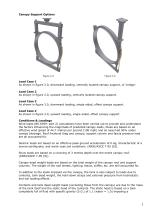
Canopy Support Options Load Case 1 As shown in figure 2.0, downward loading, centrally located canopy support, or ‘bridge’. Load Case 2 As shown in figure 2.0, upward loading, centrally located canopy support. Load Case 3 As shown in figure 3.0, downward loading, single-sided, offset canopy support. Load Case 4 As shown in figure 3.0, upward loading, single-sided, offset canopy support Conditions & Loadings Wind loads (BS.6399: part 2) calculations have been carried out to provide and understand the factors influencing the magnitude of predicted canopy loads, these are based on an effective wind...
Open the catalog to page 3
Conditions & Loadings continued… ramped pressure load to the internal surfaces of the inner tank, increasing from zero at the top of the tank to a maximum value (according to the diameter) at the bottom. In practice only a proportion of the weight of the tank will be carried by the support feet attached to the annular ring, with the remainder being supported by the additional support cradle(s) and reaction forces between the tank shell and the soil (backfill). However, this work has assumed that the support feet attached to the annular ring carry all the weight. Hold-down straps are pre-tensioned...
Open the catalog to page 4
Concrete Canopy Anchor In assessing the effect of the canopy loads on the tank, consideration has been made of the influence of the column foundation. The petrol station forecourt typically consists of a 200mm thick reinforced concrete slab, which is thickened to 500mm in a 915mm square around each support. The slab is cast around the top of the support stub column or support bridge but contains a 300mm deep by 760mm diameter pocket to maintain access to the attachment plate. Therefore, in operation the bottom of the canopy column, the bolted joint and the top of the support stub / support bridge...
Open the catalog to page 5
Remove-ability (Retract-ability) Figure 5.0 & 6.0 shows ‘joints’ between the base beams and the tank’s annular structure, this enables complete removal of the tank, if the end user wishes to reclaim the land at a much later date, thus ensuring maximum real estate protection. The ‘joints’ are also protected with phenolic spacers (Cathodic protection) FEA explanation Previously this type of calculation would probably have been done using Castigliano’s Theorem (Strain-Energy Theorem), which would have taken several weeks of calculations. “Castigliano's method, named for Carlo Alberto Castigliano,...
Open the catalog to page 6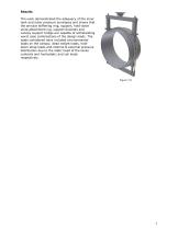
Results The work demonstrated the adequacy of the inner tank and outer pressure envelopes and shows that the annular stiffening ring, support, hold-down strap attachment lug, support brackets and canopy support bridge are capable of withstanding worst case combinations of the design loads. The loads considered have included environmental loads on the canopy, dead weight loads, holddown strap loads and internal & external pressure distribution due to the static head of the tanks contents and hydrostatic and soil loads respectively.
Open the catalog to page 7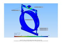
Figure 8.0, Case 1, Centrally located canopy support, downward load. Corresponding maximum vertical deflection approximately 3mm. All stresses below material yield threshold.
Open the catalog to page 8
Figure 8.1, Case 1, Centrally located canopy support, downward load, and top ring mount. Detailed view of support leg-to-circular beam junction. Peak localised stresses are approximately 70 MPa. More general circular beam & tank skin stresses are in the region of 30 MPa.
Open the catalog to page 9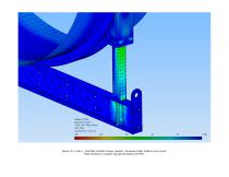
Figure 8.2, Case 1, Centrally located canopy support, downward load, bottom ring mount. Peak stresses in support leg approximately 60 MPa.
Open the catalog to page 10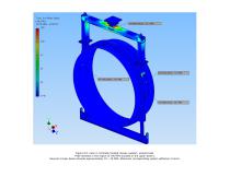
Figure 9.0, Case 2, Centrally located canopy support, upward load. Peak stresses in the region of 140 MPa (located in the upper beam). General circular beam stresses approximately 10 – 20 MPa. Maximum corresponding system deflection 3.5mm.
Open the catalog to page 11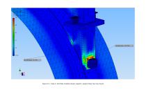
Figure 9.1, Case 2, Centrally located canopy support, upward load, top ring mount
Open the catalog to page 12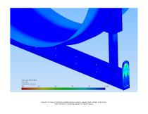
Figure 9.2, Case 2, Centrally located canopy support, upward load, bottom ring mount. Note stresses in strapping lug due to strap tension.
Open the catalog to page 13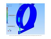
Figure 10.0, Case 3, Single-sided canopy location, downward loading. Maximum arising displacement approximately 2.5mm.
Open the catalog to page 14
Figure 10.1, Case 3, Single-sided canopy location, downward loading, top ring mount
Open the catalog to page 15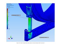
Figure 10.2, Case 3, Single-sided canopy location, downward loading, bottom ring mount
Open the catalog to page 16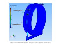
Figure 11.0, Case 4, Single-sided canopy location, upward loading. Maximum corresponding displacement approximately 1.5mm.
Open the catalog to page 17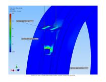
Figure 11.1, Case 4, Single-sided canopy location, upward loading, top ring mount
Open the catalog to page 18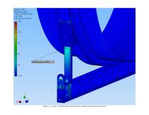
Figure 11.2, Case 4, Single-sided canopy location, upward loading, top ring mount
Open the catalog to page 19
Benefits To be of real interest to any potential client there must be visible and tangible benefits for installing PetroFast modular forecourt system over the conventional systems. It is our belief that as yet untried layouts there are major advantages and on layouts already installed in the field, we have firm figures showing substantial savings in cost and installation periods. Just to summarise some of the advantages. • Maximum amount of shop fabrication and fit out – guarantying integrity of completed system. Reduction in site installation time, in many cases by over 50%. Less complex site...
Open the catalog to page 20