
Catalog excerpts
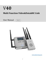
Multi Function Video&Data&RC Link User Manual
Open the catalog to page 1
1. Disclaimer Thank you for purchasing the V40 multi function video&data&RC link. Please use it in accordance with the local radio control regulations and read this statement carefully before using it. Once used, it shall be deemed to endorse and accept all contents of this statement. Please strictly follow this instruction to install and use the product. The supplier will not bear any legal liability for any result or loss caused by improper use, installation, final assembly or modification of the product. 2. Product Precautions 1. V40, the ground terminal (hereinafter referred to as...
Open the catalog to page 3
5. Please do not disassemble or modify it by yourself. If you encounter any problems during installation or use that cannot be solved, please contact Chinowing. 6. Keep the appropriate distance between the electronic devices, so as to minimize the electromagnetic interference between the devices. 7. Before use, make sure that all wiring is securely fastened and that all components are working properly. 8. In order to better serve the customers, we have been upgrading and optimizing our products, and the software and firmware will be upgraded from time to time. There may be incompatibility...
Open the catalog to page 4
4. Make sure the antennas are free from obstacle and bending in the process of use, and try to stay away from large metal to avoid the communication failure. 5. Check the ground power before use. Please stop working when the battery power is too low. Do not rely on the low battery alarm on the device, it only serves as a precaution and tells you it is time to recharge. Check the ground unit battery level each time before the use. It takes about 5-6 hours for the ground unit to be fully charged. 3. Product Introduction V40 is a multi function wireless transmission module. It can transmit...
Open the catalog to page 5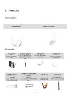
Main modules Ground unit x1 Airborne unit x 1 Accessories Charger*1
Open the catalog to page 6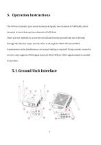
5. Operation Instructions The V40 can transmit up to seven channels of signals: two channels of S-BUS data, three channels of serial data and two channels of LAN data. There are two methods to access the serial data from the ground unit, one is directly through the data line input, and the other is through the WIFI. Wired and WIFI transmission can be simultaneous, no manual setting is required. If your remote control or receiver only supports PWM signal but not S-BUS, PWM to S-BUS signal module is needed to purchase. 5.1 Ground Unit Interface
Open the catalog to page 7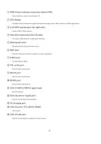
© PWR Power indicator and power button PWR Power indicator: power on and power off @ LCD display To display video transmission signal, transmission range, power, WIFI, serial port, SBUS signal status @ 2.4G WIFI antennas(on the right side) Connect SMA 2.4GHz antenna © Data link antennas(on the left side) To connect ZYJB antennas or fiber glass antennas © Waterproof cover Waterproof and dust-proofwhen no use. © RJ45 port Used for connection with the computer or other equipment @ S-BUS port 5V, GND, SBUS1, SBUS2 ® TTL serial port Used for data transmission @ RS232 port Used for data...
Open the catalog to page 8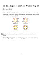
5.2 Line Sequence Chart for Aviation Plug of Ground Unit V40 ground unit provides GH interface and aviation plug interface. Only one of the interfaces can be selected for the same signal when used. The internal line sequence of the male end of the aviation plug as the following diagram 1) Welding requirements, LoTi temperature 350° ± 10°, contact time can not exceed 4 seconds. 2) Soldering TTL signals, TX needs to be connected to RX of the user device, RX needs to be connected to TX, and GND needs to be connected to GND.
Open the catalog to page 9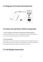
5.3 Diagram of Ground end Connection 5.4 Power On and Power off the Ground Unit short press the button, release, within 1 second long press, long press until the buzzer is 1. Power on operation: touch the power button short press plus long press over, wait for the display to light up, that means V40 is powered-on. When long press on the power button, the display will jump to the shutdown interface. At 2. Power off operation: the end of the progress bar, the shutdown is completed (about 5 seconds). If the button is released before the end of the progress bar, the shutdown will be quit.
Open the catalog to page 10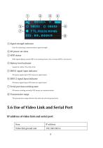
<D © Signal strength indicator Used for indicating communications signal strength @ RF power set value @ WIFI status WIFI signal display means WIFI is in working status; if no, it means WIFI is not started. © Battery level indicator Stands for 100%, 75%, 50%, 25% © SBUS1 signal input indicator ON means signal input, OFF means no signal input. © SBUS 2 signal input indicator ON means signal input, OFF means no signal input. @ Serial port data working state ON means working normally, OFF means no communications © Transmission range The transmission range between the airborne unit and ground...
Open the catalog to page 11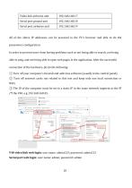
All of the above IP addresses can be accessed in the PC's browser and able to do the parameters configuration. In order to prevent users from having problems such as not being able to search, not being able to ping, and not being able to open web pages in the application. After the successful connection of the hardware, pls do the following: ® Turn off your computer's firewall and antivirus software (usually in the control panel). @ Turn off network cards not related to this test and keep only one local connection or WiFi. @ The IP of the computer must be set to a static IP in the same...
Open the catalog to page 12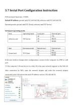
V40 serial port baud rate: 115200, Default IP address: ground unit(192.168.168.18); airborne unit(192.168.168.19) Operating mode: ground unit(TCP Client); airborne unit(TCP Server) Serial port operating mode If the user needs to change other configurations, connect to the computer via WIFI or LAN port. ® The computer's IP must be set to a static IP in the same network segment as the V40's IP. After connection by WiFi, open the network adapter and select the network adapter connected to the V40 and set the static IP address, such as 192.168.168.34.
Open the catalog to page 13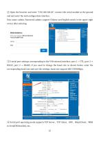
② Open the browser and enter "192.168.168.18", connect the serial module at the ground end and enter the web configuration interface. User name: admin; Password: admin; support Chinese and English switch in the upper right corner after entering. ③3 serial port settings corresponding to the V40 external interface: port 1 → TTL, port 2 → RS232, port 3 → RS485; if you need to change the baud rate as shown below, enter the corresponding baud rate and save the settings, baud rate support 600-230400bps; ④ Serial port operating mode supports TCP Server、TCP Client、UDP、Httpd Client、WEB to Serial(Web
Open the catalog to page 14


