
Catalog excerpts
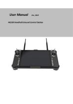
User Manual HGS30 Handheld Ground Control Station
Open the catalog to page 1
6.1 Power on and Power off of Remote Controller and the 6.2 Indicator Instruction of Remote Controller and Receiver14 6.4 Operation Instruction of V20 in Normal Connection Status 6.5 Instruction of Parameters Setting Software of Remote
Open the catalog to page 2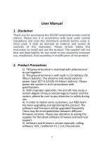
User Manual 1. Disclaimer Thank you for purchasing the HGS30 hand-held remote-control station. Please use it in accordance with local radio control regulations and read this statement carefully before using it. Once used, it shall be deemed to endorse and accept all contents of this statement. Please strictly follow this instruction to install and use the product. The supplier will not bear any legal liability for any result or loss caused by improper use, installation, final assembly or modification of the product. 2. Product Precautions 1) T30 ground terminal is matched with airborne end...
Open the catalog to page 4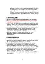
firmware: TTX 30-1.2.3-1.0; airborne end R20 firmware: RSx16-1.2.3-1.0; airborne end V20 firmware: V20RX1.2.3-1.00. 6) If you encounter any problem that cannot be solved during installation or use of the product, please contact us. 2.1 Installation Note 1. Be sure to use the spare parts provided by our company. 2. Be sure to install the antennas before power on to avoid damage to the circuit. 3. Try to make the receiver antenna without obstruction, and the end part of the antenna is vertically downward without bending, so as to avoid shortening the communication distance or even failing to...
Open the catalog to page 5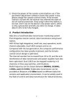
5. Check the power of the remote control before use. If the parameter adjustment software shows that power is low, please charge the remote control timely. If the remote control is turned off, the receiver has entered the state of out-of-control protection. Stop using it when the battery is too low. Don't rely on the device's low-power alarm, which is only a precaution and tells you when to charge. It takes about 5-6hs to be fully charged. 3. Product Introduction HGS-30 is a hand-held data transmission monitoring system that integrates remote control, data transmission and ground station....
Open the catalog to page 6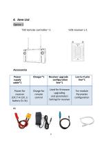
Accessories Power supply cable*1
Open the catalog to page 7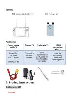
Front view
Open the catalog to page 8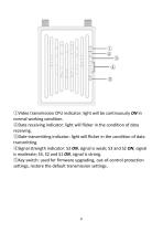
①Video transmission CPU indicator: light will be continuously ON in normal working condition. ②Data receiving indicator: light will flicker in the condition of data receiving. ③Date transmitting indicator: light will flicker in the condition of data transmitting. ④Signal strength indicator: S3 ON, signal is weak; S3 and S2 ON, signal is moderate; S3, S2 and S1 ON, signal is strong. ⑤Key switch: used for firmware upgrading, out-of-control protection settings, restore the default transmission setti
Open the catalog to page 9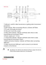
©LAN port: used for video transmission or getting video transmission parameters. ©LAN indicator: After connecting LAN port, indicator will flicker. ©TTL port: full duplex serial port ®S-Bus port: dual S-Bus output ©S-Bus1 data indicator: indicator will flicker when there is data transmitting and receiving of S-Bus1. ©Power supply port: 7.4-12v. © S-Bus2 data indicator: indicator will flicker when there is data transmitting and receiving of S-Bus2. ©WAN connection indicator: indicator will flicker when connecting WAN port. ©Video transmission WAN port: used to connect to an external network...
Open the catalog to page 10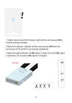
①Video transmission CPU indicator: light will be continuously ON in normal working condition. ②Data link indicator: indicator will be continuously ON when the connection of TX and RX is successfully established. ③Signal strength indicator: S3 ON, signal is weak; S3 and S2 ON, signal is moderate; S3, S2 and S1 ON, signal is strongest. Side view
Open the catalog to page 11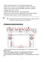
①Data transmission port: TTL, transparent transmission ②SBus 1 port: used for connecting flight controller or payload ③SBus 2 port: used for connecting flight controller or payload ④Power supply port: 7.4-12V ⑤HDMI video input interface: connecting camera ⑥USB port: used for firmware upgrading and parameters setting ⑦AV video input interface: used for analog video input. By default, the S-BUS1 and S-BUS2 interfaces output the CH1 to CH16 of the remote control to 1-16 channels. 5.3 Remote Control Instruction ①Left and right rockers: corresponding T1, T2, T3 and T4, used for flight control...
Open the catalog to page 12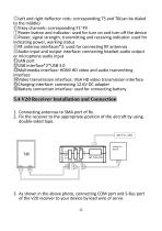
©Left and right deflector rods: corresponding T5 and T6(can be dialed to the middle) ©9 key channels: corresponding F1~F9 ©Power button and indicator: used for turn on and turn off the device ©Power, signal strength, transmitting and receiving indicator: used for indicating power, working status ©RF antenna interfaces*2: used for connecting RF antennas ©Aud io input and output interface: connecting headset audio output or microphone audio input ©LAN port ©USB interface*2*USB 3.0 ©Multimedia interface: HDMI HD video and audio transmitting interface ©Video transmission interface: VGA HD video...
Open the catalog to page 13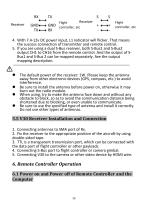
4. With 7.4-12v DC power input, L1 indicator will flicker. That means the success connection of transmitter and remote control. 5. If you are using a dual S-Bus receiver, both S-Bus1 and S-Bus2 output CH1 to CH16 from the remote control. And the output of SBus1 and S-Bus 2 can be mapped separately. See the output mapping description. The default power of the receiver: 1W. Please keep the antenna away from other electronic devices (GPS, compass, etc.) to avoid interference. Be sure to install the antenna before power on, otherwise it may burn out the radio module. When using, try to...
Open the catalog to page 14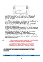
In the process of turning on/off the device T30 , please pay attention to the power button, power indicator and 4 power indicators (25%,50%,75%,100%) and 5 data link indicators (RS1,RS2,RS3,TX,RX). 1. Long press the power button, the power indicator light is on, and then according to the speed of the release action of the button to decide whether the computer is turned on or not. 2. Release the power button after the first short sound of the buzzer. At this time, the remote control is switched on and the computer is not switched on. 3. After hearing the second short sound of the buzzer,...
Open the catalog to page 15


