
Catalog excerpts
T18 Handheld GCS User manual 2020.11
Open the catalog to page 1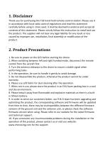
1. Disclaimer Thank you for purchasing the T18 hand-held remote-control station. Please use it in accordance with local radio control regulations and read this statement carefully before using it. Once used, it shall be deemed to endorse and accept all contents of this statement. Please strictly follow this instruction to install and use the product. The supplier will not bear any legal liability for any result or loss caused by improper use, installation, final assembly or modification of the product. 2. Product Precautions 1. Be sure to power on the GCS before starting the drone. 2. When...
Open the catalog to page 3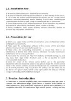
2.1. Installation Note 1) Be sure to use the spare parts provided by our company. 2) Be sure to install the antennas before power on to avoid damage to the circuit. 3) Try to make the receiver antenna without obstruction, and the end part of the antenna is vertically downward without bending, so as to avoid shortening the communication distance or even failing to communicate due to obstruction. 4) Do not disassemble or refit without permission. If you encounter any problem that cannot be solved during installation, please contact us directly. 5) During installation, keep proper distance...
Open the catalog to page 4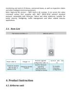
monitoring and control of drones, unmanned boats, as well as inspection robots and other intelligent terminal equipment. Note: High-end 4G version -- With built-in 4G module, it can access the video command system that complies with GB/T 28181-2016 national standard protocol, compatible with Hikvision, Dahua and other platforms, suitable for public security, firefighting, traffic management and other related industry applications.
Open the catalog to page 5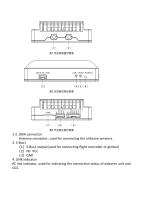
1-2. SMA connector Antenna connector, used for connecting the airborne antenna. 3. S-Bus1 (1)S-Bus1 output(used for connecting flight controller or gimbal) (2)Nc: VCC (3)GND 4. LINK indicator RC link indicator, used for indicating the connection status of airborne unit
Open the catalog to page 6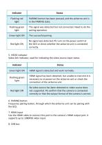
6. PAIRING button Frequency pairing button, through which the airborne unit can be pairing with the GCS. 7. HDMI input Use the HDMI cable to connect this port to the camera's HDMI output port. It supports up to 1080P60 video input.
Open the catalog to page 7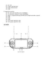
(1)NC: VCC (2)CANH: CAN high level (3)CANL: CAN low level (4)GND 9. Integration interface (1)Rx: serial port input(TTL Level, 115200bps) (2)Tx: serial port output(TTL Level, 115200bps) (3)SBUS 2: output(connecting the SBUS port of flight controller or gimal) (4)GND (5)GND (6)GND (7)12V: power input(4.5v-16v) (8)12V: power
Open the catalog to page 8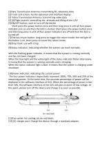
[1]Data Transmission Antenna: transmitting RC, telemetry data [2]7 inch LCD screen: for the operation and interface display [3] Video Transmission Antenna: transmitting video data [4] [6]Flight joystick: controlling the attitude and lifting of the UAV [5]ON/OFF button: start or turn off the device Short press the power button once and then long press it until all four power indicators are on and then the GCS is started. Short press the power button once and then long press it until all four power indicators are off and then the GCS is turned off. [7]One key return button: long press to...
Open the catalog to page 9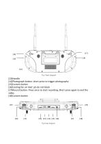
[13]Handle [14]Photograph button: short press to trigger photography [15]Custom button [16]Cooling fan air inlet: pls do not block [17]Record button: Press once to start recording; Short press again to end the video. [18]Custom button [19]
Open the catalog to page 10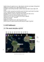
[19]Pull wheel for gimbal course: adjusting the direction and angle of the gimbal [20]Button for gimbal zoom: adjusting gimbal zoom [21]Flight mode shifting lever①H: altitude hold mode ②G: reserve ③A: GPS mode [22]micro SIM: reserved function(4G version for choice); pull wheel for gimbal course: adjusting direction and angle of the gimbal [23]USB interface: external U disk and other devices for data access; [24]HDMI: to connect external display, copy screen; [25]micro SD: for external storage and firmware upgrade [26]UART serial port:reserved [27]Custom button [28]Button for gimbal zoom:...
Open the catalog to page 11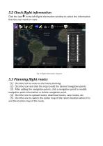
5.2 Check flight information Click the icon in the left flight information window to select the information that the user needs to view. Fig 10 flight information diagram 5.3 Planning flight routes (1)Click the icon to enter to the route planning (2)Click the icon and click the map to add the desired navigation points (3)After adding the navigation points, click a navigation point to modify navigation point information or delete navigation point. (4)Click the icon to upload routes, download routes, save routes, etc. (5)Click the icon to switch the center map of the return location where H...
Open the catalog to page 12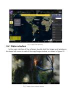
Fig 11 Flight route planning interface In the main interface of the software, double-click the image small window in the lower left corner to switch the map/image window, as shown in Figure 12. Fig 12 Image window enlarge interface
Open the catalog to page 13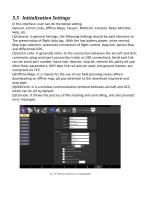
5.5 Initialization Settings In this interface, user can do the below setting General, Comm Links, Offline Maps, Taisync, MAVLink, Console, Radui Member, Help, etc. (1)General: In general Settings, the following Settings should be paid attention to. The preservation of flight data log;. With the low battery power, voice remind; Map type selection; Automatic connection of flight control, data link, optical flow and differential GPS. (2)Comm Links: It generally refers to the connection between the aircraft and GCS, commonly using serial port connection (radio or USB connection); Serial port...
Open the catalog to page 14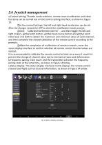
5.6 Joystick management a.Control setting: Throttle mode selection, remote control calibration and other functions can be carried out on the control setting interface, as shown in Figure 13: ①In the control Settings, the left and right hand accelerator can be set. After the change, restart the APP to check the modification result prompt; ②Click ‘Calibrate the Remote control’, and then toggle the left and right rockers, gimbal pitch button, gimbal head course button and gimbal zoom roller back and forth to obtain the maximum and minimum value of each channel, and then complete the channel...
Open the catalog to page 15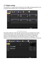
5.7 Flight setting (1) Summary: It is mainly used to preview the main flight setting parameters so as to quickly check whether there is any setting error or omission. Fig 15 Flight setting interface (2)Joystick calibration: Take the right-hand throttle as an example: First, make sure that the receiver of the remote control is connected correctly with the remote control signal input end of the flight control. Click the "Calibration" button to start the calibration and follow the prompts for calibration. This interface can switch among American hand, Japanese hand and Chinese hand, etc.
Open the catalog to page 16


