3401-001 D*M High Density

3401-001 D*M High Density
Specifications: The connectors feature solder cup, straight PCB solder, and 90° bent PCB solder terminations, with contact configurations ranging from 15 to 104 ways. They are individually packaged with a dust cap for ESA/ESCC quality level connectors.
Ordering Information: Detailed instructions are provided for ordering connectors based on quality levels (ESA/ESCC, FR023, FR022), including termination modifiers, shell finishes, magnetism levels, and contact types. Fixing options include standard through hole, captive nut, or dual float mount.
Dimensions and Weights: Specific dimensions are given for each shell size, with maximum and minimum values for pin diameter and length. Maximum weights for male and female connectors without contacts or accessories are also listed.
Termination Types: Various termination types are described, including solder bucket, straight PCB solder, and 90° bent PCB solder with or without brackets, along with specific dimensions for each type and shell size.
Cross References: Cross-reference tables for ESA/ESCC and FR022 part numbers are included, detailing configurations and options for each quality level.
Recommendations: Wire stripping instructions recommend using insulated wires of sizes AWG 22, 24, and 26, with AWG 28 being possible but not ESA-approved.
Procedures: Consultation with the factory is recommended for specific termination modifiers. Users should verify current specifications on the manufacturer's website as dimensions are subject to change.
Standards and Recommendations: Recommended PCB hole sizes are provided for signal contacts, with different specifications for M2 and OL3 terminations. Weight specifications are detailed for both male and female contacts, as well as for brackets.
Additional Information: FR023 parts are available upon request only. All dimensions and specifications are subject to revision as of April 23, 2013.
Catalog excerpts

Features/Benefits • D*Sub Connector Type • Contacts installed in factory • Multiple contacts configuration: solder cup 90° bent and straight PCB contact • From 15 to 104 ways Typical Applications • Payloads PCB • Launchers • PCB Test Connectors with solder type termination contacts size 22 inserted into two-piece insulators. Termination types available: - Solder cup - Straight PCB solder terminations - 90° bent PCB solder terminations Packaging unit: 1 piece (plastic bag) Dust cap supplied with each connector, only for quality level ESA/ESCC Solder bucket: accepted wire sizes: insulated AWG 22, 24, 26 and 28 How to order - ESA/ESCC Quality Level Detail specification number Variant- 02: High density Testing level - Shell size E A B C D F Insert type: M for two-piece insert- Nothing: Standard through hole E: Captive nut Y: Dual float mount Fixing option E or Y not compatible with connectors equipped with bracket. Termination modifier Nothing: solder bucket contacts Straight PCB: OL3 90° bent PCB without brackets 1C0N, 1D0N 90° bent PCB with brackets 1C7N, 1C9N, 1D7N, 1D9N (size D & F only) Nothing: solder cup Shell Finish for F size only: • A174 (25.4pm Ni) • FR172 (0.7 pm gold over 25.4 pm Ni) Magnetism level NMB: 200 Gamma NMC: 20 Gamma (on special request) Type of contact P: Pin (Male) S: Socket (Female) Contact arrangement (number of contacts) E: 15 A: 26 B: 44 C: 62 D: 78 F: 104 Dimensions are shown in mm (inch) Dimensions subject to change
Open the catalog to page 1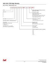
How to order - FR023 Quality Level Series — Shell size E A B C D F Suffix for MIL Class M Quality (Connector Specification FR023) — Termination modifier Nothing: solder bucket contacts Straight PCB: OL3, M2 90° bent PCB without brackets 1C0N, 1D0N 90° bent PCB with brackets 1C7N, 1C9N, 1D7N, 1D9N (size D & F only) Insert type: M for two-piece insert According to MIL-DTL-24308 Specification Fixing option: Nothing: Standard through hole E: Captive nut Y: Dual float mount Fixing option E or Y not compatible with connectors equipped with bracket Shell Finish for F size only: • A174 (25.4um Ni) •...
Open the catalog to page 2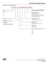
Series — Shell size E A B C D F Suffix for Commercial Space Grade Quality Level (Connector Specification FR022) - Termination modifier Nothing: solder bucket contacts Straight PCB: OL3, M2 90° bent PCB without brackets 1C0N, 1D0N 90° bent PCB with brackets 1C7N, 1C9N, 1D7N, 1D9N (size D & F only) Insert type: M for two-piece insert- Fixing option: - Nothing: Standard through hole E: Captive nut Y: Dual float mount Fixing option E or Y not compatible with connectors equipped with bracket. Shell Finish for F size only: • A174 (25.4um Ni) • FR172: (0.7 um gold over 25.4 um Ni) Magnetism level NMB:...
Open the catalog to page 3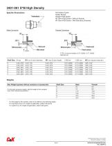
Specific Dimensions Male Connector Termination Types: Solder Bucket Straight PCB Solder 90° Bent PCB Solder / Without Bracket 90° Bent PCB Solder / With Monobloc Brackets Female Connector Reference plane — Male insert Reference plane Male contact Female contact 0 Z2: to accommodate a 0,75 (.0295) / 0,77 (.0305) diameter pin Shell Size V max W1 min (Full pin diameter) W1 max (Full pin length) 0 Z1 min 0 Z1 max W2 min (Square ended pin) E0,40 (.016) 4,43 (.174)5,45 (.215)0,75 (.0295) 0,77 (.0305) 3,63 (.143) Max Weight (grams) without contacts or accessoriesShell SizeMaleFemale...
Open the catalog to page 4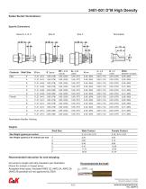
Sizes E, A, B, C Size D Size F Termination J ± 0,3 K ± 0,1 Pitch Contacts Shell Size D Max E Typical 000^^j^3 G0^'55 H min Max Weight (grams) per contact Max Weight (grams) of all contacts per size E A B C D F Recommended instruction for wire stripping: Cut wires to length and strip insulation per illustration. Check for broken or frayed wires. Accepted wires sizes: insulated AWG 22, AWG 24, AWG 26. (AWG 28 possible but not approved by ESA) Dimensions are shown in mm (inch) Dimensions subject to change
Open the catalog to page 5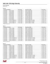
*FR023 under request only Dimensions are shown in mm (inch) Dimensions subject to change
Open the catalog to page 6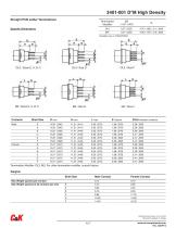
Straight PCB solder Terminations Specific Dimensions Contacts Shell Size D max H max L max Pitch between contacts 2,29 (.090)_ Shell Size Male Contact Max Weight (grams) per contact 0,14 Max Weight (grams) of all contacts per size E 2,10 Female Contact Dimensions are shown in mm (inch) Dimensions subject to change
Open the catalog to page 7
FR023 under request only Dimensions are shown in mm (inch) Dimensions subject to change
Open the catalog to page 8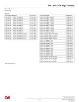
FR023 under request only Dimensions are shown in mm (inch) Dimensions subject to change
Open the catalog to page 9
FR023 under request only Dimensions are shown in mm (inch) Dimensions subject to change
Open the catalog to page 10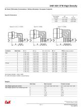
Size D (1 DON) Size F (1 DON) Contacts Shell Size D min D max G ± 0,30 (.012) M min Pitch between contacts Max Weight (grams) per contact Max Weight (grams) of all contacts per size E A B C D F Dimensions are shown in mm (inch) Dimensions subject to change
Open the catalog to page 11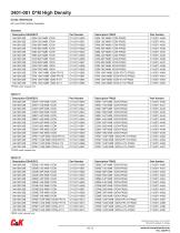
Cross references 90° bent PCB (without brackets) FR023 under request only Dimensions are shown in mm (inch) Dimensions subject to change
Open the catalog to page 12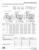
Specific Dimensions 2 pieces metal brackets: “7N”: fixed with captive nuts 4-40 UNC-2B “9N”: fixed with captive nuts M3 Oval hole 0 I: 3,22 (.127) ± 0,10 (.004) x 4,90 (.193) ± 0,10 (.004) Termination Modifier: 1C7N, 1D7N, 1C9N, 1D9N For other termination modifier, consult factory Weights Shell Size Male Contact Female Contact Max Weight (grams) of all contacts per size E 2,70 3,45 _A4,706,00 _B7,9410,14 _C11,1814,28 _D14,8418,74 F20,8426,04 Max Weight (grams) of Brackets E, A, B, C 3,95 3,95 Dimensions are shown in mm (inch) Dimensions subject to change
Open the catalog to page 13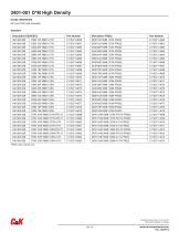
Cross references 90° bent PCB (with brackets) FR023 under request only Dimensions are shown in mm (inch) Dimensions subject to change
Open the catalog to page 14
PCB Hole Pattern Face view, pin insert for plug) (use a mirror image for receptacle [Mating side) [Mating side) (Mating side) (Mating side) (Mating side) Dimension X • 1,98 (.078) for sizes E, A, B, C • 2,08 (.082) for size D and F Recommended PC hole for signal contacts • 0 0,90 (.035) min for terminations 0 0,51 (.020) (M2) Termination • 0 1,00 (.040) min for terminations 0 0,57 (.022) (OL3) Termination Dimensions are shown in mm (inch) Dimensions subject to change
Open the catalog to page 15All C & K catalogs and technical brochures
 CCM03 MK2 Series
15 Pages
 DS Series Detect Switch
5 Pages
 KSJ Detect Series
2 Pages
 Filter Connectors / D*J
12 Pages
 3401-001 D*M Standard Density
28 Pages


- Aircraft connector
- Data connector
- Rectangular connector
- Board connector
- Coaxial connector
- Crimp connector
- Electrical power supply connector
- MiL connector
- High-density connector
- Miniature connector
- Straight connector
- Micro-miniature connector
- D-sub connector
- Micro-D connector
- Plug-in connector
- Large connector
- Male-female connector
- Snap-on connector