- Catalogs
- AveoEngineering s.r.o.
- Pegatron
Pegatron

Pegatron
This document is the installation manual for the Pegatron™ LED position light assembly, designed for aircraft tail positions. It is compliant with EASA ETSO standards and includes part numbers AVE-POSW-74G-401, -402, and -403.
- Approval: Established under EASA AP429, approved by Georg Hartl on 27-Oct-2016.
- Amendment Record: Lists changes and updates, with the latest issue on 27-Oct-2016.
- Distribution: Controlled electronically by Aveo Engineering Group, with a master copy maintained.
- Dimensions: 47 x 57 x 35 mm (1.85” x 2.24” x 1.38”).
- Weight: 106g.
- Operating Voltage: 18-36V DC, with primary input at 28V DC.
- Protection: Over-voltage (80V for 1s), reverse polarity, over-temperature, waterproof, vibration-proof, shock-proof, and dust-proof.
- Wiring: Positive and ground connections are specified.
- Testing: Conducted with a 24V/5A DC power supply. Use of inappropriate power sources voids warranty.
- Installation: Even distribution of tightening forces is recommended, using stainless steel screws.
- Cleaning: Use automotive polish and avoid petroleum-based products. For UV protection, use Nonocloak™ UV Protectant Spray.
- Reporting: Operators must report occurrences to Aveo Engineering within 72 hours using EASA Form1.
- Inspection: Regular checks during preflight and annual inspections are required. Use polarized sunglasses for safety when inspecting LEDs.
Catalog excerpts

INSTALLATION MANUAL © 2015 Aveo Engineering Group, s.r.o. All rights reserved. The information contained within this document must not be disclosed, copied or reproduced in whole or in part without prior written permission from Aveo Engineering Group, s.r.o. Distribution of this document shall only be as stated in Table 02 unless otherwise agreed by Aveo Engineering Group, s.r.o.
Open the catalog to page 1
Installation Manual Manual Administration 0.1 Table of Contents PART 0 MANUAL ADMINISTRATION DOCUMENT APPROVAL AMENDMENT RECORD PROCEDURE EFFECTED PAGES PROCEDURE DISTRIBUTION LIST OPERATING INSTRUCTIONS INSTALLATION SCHEMATIC / WIRING DIAGRAM CONTROL & POWER INPUT’S: TECHNICAL SPECIFICATION TECHNICAL DRAWING WIRING CHART EQUIPMENT LIMITATION TESTING OF THE LIGHT BEFORE INSTALLATION CARE AND CLEANING OF YOUR AVEO ENGINEERING AVIATION LIGHTS CONTINUED AIRWORTHINESS INFORMATION
Open the catalog to page 2
Installation Manual 0.2 Document approval This document has been established in accordance with an alternative procedure to DOA approved under EASA AP429. This installation manual is according EASA ETSO 21O.10055101 and applicable for part number AVE-POSW-74G-401, -402 and -403. Peter Nezval Engineer, Aveo Engineering Group, s.r.o. Georg Hartl Head of DO, Aveo Engineering Group, s.r.o. 0.3 Amendment Record procedure The master copy of this document shall be kept electronically as a read only document under the control of Aveo Engineering Group, s.r.o. as Master Copy. ALL amendments to this manual...
Open the catalog to page 3
Installation Manual 0.4 Effected Pages Procedure ALL pages affected by ANY raise of issue of this manual will be listed in Table 01 - Effected Pages Column. The reason(s) for ALL raise of issue and description of change due to raise of issue will be provided for ALL raises of issue in Table 01 - Details Column. Changes from the previous issue are highlighted by YELLOW HIGHLIGHTING over new content. AND YELLOW HIGHLIGHTING AND CROSSING OUT of deleted content. Example (CROSSING OUT) As stated in 0.3 above; the master copy of this document shall be kept electronically as a read only document under...
Open the catalog to page 4
Installation Manual Pegatron™ is a LED position light assembly E TSO Compliant white position lights low drag and low profile designed for aircraft tail position. This powerful LED lighting system features easy installation, a fail save system, unbreakable construction, waterproof and high candela output. List of the major components (by part number) that make up the equipment complying with the standards prescribed in ETSO. • P/N: AVE-POSW-74G-401 (White) P/N: AVE-POSW-74G-402 (White) P/N: AVE-POSW-74G-403 (White) Figure 01: Features of Pegatron OPERATING INSTRUCTIONS When installed on the aircraft,...
Open the catalog to page 5
Installation Manual CONTROL & POWER INPUT’s: POSITIVE POLE GND POLE Positive POS/NAV power supply line Negative common power supply line (ground) TECHNICAL SPECIFICATION Dimensions (mm): Dimensions (inches): Weight (g): Operating voltage: Primary input voltage: Over-voltage protection: Input current at 28V: Reverse polarity protection: Over-Voltage shut down: Operating temperature: Over-Temperature protection: Output power Waterproof: Vibration-proof: Shock-proof: Dust-proof:
Open the catalog to page 6
Installation Manual TECHNICAL DRAWING Dimensions are in millimeters / [inches] _______________________________________________________________________________________________________________________ Page 7 of 12
Open the catalog to page 7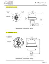
Installation Manual Dimensions are in millimeters / [inches] Dimensions are in millimeters / [inches] _______________________________________________________________________________________________________________________ Page 8 of 12
Open the catalog to page 8
Installation Manual WIRING CHART EQUIPMENT LIMITATION Pegatron™ should only be powered by 18-36 Vdc, typically a 24 volt aircraft battery. TESTING OF THE LIGHT BEFORE INSTALLATION All Aveo Aviation lights undergo rigorous testing prior to being released from our engineering manufacturing department. This testing involves a burn-in time as well as other function testing. No light is released for sale without undergoing this extensive operational testing. When you receive the Pegatron™ light, and wish to test the function of the light prior to installation on your aircraft, please note the following:...
Open the catalog to page 9
Installation Manual 3. Testing the function of the light can be done with a regular 24V/5A dc power supply (no battery chargers). Connect the black wire to the ground (negative) leads of a power supply, then connect the yellow wire to the positive (+) leads on the power supply. The position light should start lighting. When installed on the aircraft, using the aircraft’s power (28 volts), the light will be at its maximum intensity. After testing, the light can be installed on the aircraft. IMPORTANT NOTES: 1. Under no circumstances should any power supply other than a 18-36 Vdc, or a 24 volt...
Open the catalog to page 10
Installation Manual Spread the tightening forces evenly around the mounting hole. Stainless steel screw is recommended. Length depends upon placement location on aircraft. 12. CONTINUED AIRWORTHINESS INFORMATION This product is delivered with EASA Form1 which is for the operator to report any occurrences to Aveo Engineering as the ETSO holder. The form contains the Aveo Engineering telephone number and the occurrence e-mail address ([email protected]). The operator must report immediately as the ETSO holder must report occurrences having a potential for an unsafe condition within...
Open the catalog to page 11
Installation Manual Figure 2: Position LEDs – all LEDs (12 pcs)
Open the catalog to page 12All AveoEngineering s.r.o. catalogs and technical brochures
 PosiStrobe CP
12 Pages
 Samson Drop-In Plus
8 Pages
 RedBaron Combo HISL Galactica
16 Pages
 RedBaron XP Galactica
16 Pages
 SmartStrobe
13 Pages
 Samson Drop-In
16 Pages
 Gulfstream Replacement
2 Pages
 Installation Manual
10 Pages
 Ultra Galactica Embedded
2 Pages
 Ultra Galactica
13 Pages
 Mooney M20 Installation Manual
21 Pages
 Brochure
4 Pages
 AVE-CCPS-01-IM
12 Pages
 Atlas 10
10 Pages
 Exceleron DayLite
13 Pages
 HerculesDropInPlus.
3 Pages
 Hercules H30
9 Pages
 /Hercules
11 Pages
 StrobeTailNano
6 Pages
 POSISTROBE DAYLITE
2 Pages
 PosiTail Nano
6 Pages
 RedBaron MaxiMini
7 Pages
 PosiStrobe MiniMax
5 Pages
 RedBaron XP DayLite
1 Page
 RedBaron Mini DayLite
2 Pages
 PICOMAX
1 Page
 GLIDERBURST DAYLITE
1 Page
 Andromeda DayLite
1 Page
 Ultra DayLite
2 Pages
 Ultra Embedded DayLite
2 Pages
