


SIM connectors

SIM connectors
- SIM Serie II Connectors: These are modular, rectangular, multi-contact, and multifunctional connectors available in metallic or composite versions. They are qualified according to EN 4165 standards and offer two shell types (2 or 4 modules) and two mating types (clicker nut and rack panel plug).
- 1900SIM Connectors: This section provides technical data, part numbering, and details on plugs, receptacles, and accessories.
- Monomodule SIM Connectors: Focuses on single-module connectors, including technical data and part numbering.
- SIM Splice: Describes standard and specialized versions of SIM splices, including those with cable clamps and flanges.
- Optical SIM Serie II Connectors: Details on optical connectors, including product availability and compatibility with optical modules.
- Optical Monomodule SIM Connectors: Information on single-module optical connectors and their components.
- Optical Modules and Contacts: Covers various optical modules and contacts, including LUXCIS®, AMPHELUX®, and SIMTac®.
- Tools: Lists tools for contacts, modules, and specific connector series.
- Instructions for SIM II Series Connector: Provides detailed assembly and disassembly instructions for various components.
- Instructions for 1900SIM and Monomodule SIM Connectors: Includes procedures for insertion, extraction, and mounting of modules and connectors.
- Wiring Instructions: Offers guidance on wiring electrical contacts and handling optical termini.
- Contains a comprehensive part number table for reference.
- Modular design allows for flexibility and customization.
- Available in both metallic and composite materials, with options for shielding.
- Complies with international standards such as EN 4165 and SAE-AS39029.
- Wide range of accessories and tools to support installation and maintenance.
- Polarization: Ensured by an asymmetrical mounting screw and a polarizing system with 36 keying combinations.
- Materials: Available in metallic (aluminum alloy) and composite (thermoplastic) versions.
- Plating Options: Black nickel, bright nickel, olive drab cadmium, and nickel PTFE (consultation required).
- Shielding Effectiveness: 50 dB at 100 MHz and 30 dB at 1 GHz for shielded versions.
- Environmental Resistance: Operating temperature from -55°C to +175°C, IP66/IP68/IP69K sealing, and salt spray resistance.
- Electrical Properties: Insulation resistance ≥ 5000 MΩ, withstanding voltage of 1800 V at 50 Hz, and metallization resistance varying by material and plating.
Modules and Contacts
- Modules: Made of thermoplastic and overmoulded silicon elastomer, available in pin and socket types.
- Contacts: Compliant with SAE-AS39029 and EN3155 standards, available in sizes 23 to 8, and designed for specific contacts like coaxial, fiber optic, etc.
Mechanical and Environmental Performance
- Endurance: 500 full mating and unmating cycles.
- Vibration and Shock Resistance: Random frequency from 10 to 2000 Hz, 100 gn shock amplitude.
- Sealing: Excellent sealing ensured by elastomer barriers and overmoulded elastomer on pin modules.
Applications and Accessories
- Compatible with connectors complying with MBBN 3330 and EN4165 standards.
- Available rear accessories include covers and cable clamps.
Visual Aids
The document includes exploded views and synoptic diagrams of various connector configurations, illustrating the assembly and components of both metallic and composite connectors.
- Material: Thermoplastic shells with options for bright nickel, olive drab cadmium, or no plating.
- Modules: Made from thermoplastic and silicone elastomer.
- Contacts: Copper alloy with gold on nickel plating, available in sizes 23 to 8.
- Retention: Modules retention in shell is ≥ 25.4 daN.
- Endurance: 100 full mating/unmating cycles.
- Vibrations: Sinusoidal, 5 to 3000 Hz, 20g acceleration.
- Shocks: 6 shocks per direction, 50g amplitude, 11ms duration.
- Operating Temperature: -55°C to +175°C.
- Sealing: IP66 rated, with specific tests for intercavity and interfacial sealing.
- Insulation Resistance: ≥ 5000 MΩ.
- Metallization: Conductive plating ensures continuity, with specific resistance values under 1A per connection.
The SIM mono module is an extension of the AECMA/EN 4165 modular, rectangular series, designed according to ARINC 809 recommendations. It supports various contact types including signal, power, coax, twinax, triax, quadrax, optical termini, and RJ45 Ethernet.
Module Specifications
The modules are available in EN4165 sizes and are sealed when mated. Male modules feature interfacial and grommet seals, while female modules have a grommet. They include a polarization system compatible with connector polarizations. Modules are inserted from the rear and require a specific tool for extraction.
Contact Specifications
Pin and socket crimp contacts comply with SAE-AS39029 and EN3155 standards, available in sizes 23 to 8. Contacts are inserted through the grommet surface, ensuring excellent sealing with three elastic barriers. Mating side sealing is ensured by overmolded elastomer on pin modules.
Technical Data
Mechanical: Composite shell material with nickel plating, module retention ≥ 25.4 daN, contact retention, 500 mating cycles, vibration resistance from 10 to 2000 Hz, shock resistance of 100 gn for 6 ms.
Environmental: Operating temperature from -55°C to +175°C, salt spray resistance for 500 hours.
Sealing: IP66/IP68/IP69K, interfacial sealing according to EN 2591, air leakage ≤ 4 cm³/h under 1 bar pressure.
Electrical: Insulation resistance ≥ 5000 MΩ, metallization continuity with resistance < 3 mΩ at 1 Amp.
Part Numbering System
Includes options for plating, shell type, coupling polarization, color coding plate, panel sealing, nut plate, and protection cap. Various configurations are available for different applications.
Accessories
Includes backshells, protection caps, and color coding plates. Options for metallized and non-metallized versions are available.
Polarization and Color Coding
Polarization is mechanical with visual aid provided by a color system. Associated colors are used between coupling polarization and plates.
Figures 13 to 15 provide the general dimensions for panel cut outs, free mounting cut outs, and oriented panel cut outs. Key measurements include diameters and radii with tolerances, ensuring precise fitting for various applications.
These dimensions apply to all polarization versions, ensuring compatibility across different configurations.
The document lists various SIM connectors and accessories, detailing their part numbers, descriptions, and weights. Products include plugs, receptacles, backshells, and protection caps, each designed for specific applications and environments.
The SIM Splice system allows for efficient connection between SIM modules, available in standard, cable clamp, and flanged versions. Modules are made from thermoplastic and silicone elastomer, designed to handle power, signal, and optical connections while ensuring sealing and polarization compatibility.
Mechanical properties include material specifications, retention forces, endurance, vibration, and shock resistance. Environmental specifications cover operating temperatures and sealing standards (IP66/IP68/IP69K). Electrical specifications include insulation resistance and current ratings for various contact sizes.
The document outlines the part numbering system for SIM Splice and modules, detailing options for protection plating, accessories, fixing methods, and polarization.
Amphenol Air LB offers a range of overmolded modules designed for optimal sealing and voltage resistance. Modules accommodate various contact types and sizes, adhering to SAE-AS39029 and EN3155 standards. Polarization is achieved through specific design features within connector cavities.
The document outlines various modules and contacts, including crimped contacts for Alu cables and MIL39029 contacts delivered by default. It specifies male (Pin P) and female (Socket S) contacts, with polarization options N, A, B, C, D. Modules can be supplied with or without contacts, and specific contact types are recommended for certain modules.
Procedures:
Modules for crimped contacts are detailed, including those for angled PCB contacts, which are available with N polarization only. The document specifies that certain modules are not available with layout 1602.
Standards and Norms:
Contact plating options include tin-plated with or without lead (RoHS compliant) and gold-plated (RoHS compliant). The document also includes RJ45 Ethernet module specifications, compliant with network standards such as 10BASE-T, 100BASE-TX, and 10GBASE-T.
Recommendations:
For high-density contacts, green modules are recommended, while grey modules are suggested for crimped contacts with Alu cables. The document advises consulting for other part numbers.
Test Reports:
Test reports for RJ45 Class C and Class Ea are included, detailing headroom, frequency, and compliance with ISO11801 standards. The reports confirm compliance with various network standards and provide detailed test results, including NEXT, ACR-N, and RL values.
Key Data from Tables and Graphs:
The document includes detailed test data for insertion loss, NEXT, ACR-F, and ACR-N across various frequencies, confirming compliance with specified limits. Graphs illustrate performance metrics across frequency ranges, supporting the test results.
The document provides detailed specifications for various modules and contacts used in high-speed Ethernet data transmission and power supply. It includes information on withstanding voltage (1500 V eff. 50 Hz), insulation resistance (>5000 MΩ), and maximum current ratings for different contact sizes (#26: 3 A, #22: 5.4 A, #16: 15 A). The operating temperature range is from -55°C to +175°C.
Module Configurations:
The document describes modules for high-speed Cat 5E Ethernet data transmission and power, allowing Ethernet links and power supply in a single EN4165 form factor insert. Configurations include 6 contacts size 16, 2 contacts size 22, and 8 contacts size 26. Three types of modules are available: crimped contacts, straight PCB contacts, and angled PCB contacts.
Compliance and Standards:
The modules comply with network standards such as 10BASE-T, 100BASE-TX, 100BASE-T4, 1000BASE-T, 10GBASE-T, ATM-25, ATM-51, ATM-155, 100VG-AnyLan, TR-4, TR-16 Active, and TR-16 Passive.
Performance Metrics:
The document includes performance metrics such as Return Loss (RL), Near-End Crosstalk (NEXT), Power Sum NEXT (PS NEXT), Attenuation to Crosstalk Ratio Far-end (ACR-F), and Power Sum ACR-F (PS ACR-F) across various frequencies (MHz) with specified limits (dB).
Module Types and Features:
The document details different module types, including male and female modules with straight and angled PCB contacts, crimped contacts, and grounding modules. It also covers shunt modules and their configurations.
Contact and Plating Options:
Various contact sizes and plating options are available, including tin-plated with lead, tin-plated without lead (RoHS), and gold-plated (RoHS). The document also provides information on peripheral sealing and polarization options.
Additional Components:
The document includes information on sealing plugs, dummy contacts, and PCB layout details for modules with straight and angled PCB contacts.
This document is a technical datasheet from Amphenol Air LB, detailing the specifications and configurations of SIM Series II connectors. It includes information on optical composite and metallic connectors, available in 2 and 4 module configurations.
Specifications
- The connectors are available in both composite and metallic materials, with options for standard and shielded versions.
- Operating temperature range is from -60°C to +175°C.
- The connectors are designed for mounting under panels only, and compatibility with equipment must be verified.
Components and Configurations
- The document lists various components such as optical plugs, receptacle covers, clicker nuts, and silicone caps.
- Connectors are available in short and long shell types, with specific part numbers provided for each configuration.
- The document includes a part numbering system to identify different configurations based on material, shell type, polarization, and plating.
Mounting and Compatibility
- The document advises consulting Amphenol for use on plates and checking mounting compatibility with equipment.
- Panel cutout dimensions and tightening torque specifications are provided for proper installation.
Additional Information
- The document includes references to additional pages for part numbering and compatibility details.
- It emphasizes that the datasheet is proprietary to Amphenol Air LB and cannot be reproduced without authorization.
The SIM Monomodule optical connector is a modular and rectangular connector designed for optical fiber use. It features flanged receptacles and standard push-pull locking plugs, with specific rear accessories for optical fiber compatibility. The connectors are available in composite versions, either unplated or nickel-plated for electrical continuity and shielding effectiveness.
Specifications and Features
- Mechanical coupling polarization from A to G, identified by color coding.
- Modular design simplifies termination, assembly, installation, maintenance, and repair.
- Qualified to EN4165 standards and designed according to ARINC 809 recommendations.
Optical Modules
The SIM Monomodule range is compatible with optical SIM modules made from thermoplastic and overmolded silicon elastomer. These modules include a polarization system and ensure optical connection through male and female modules inserted from the rear of the shells. Extraction requires a specific tool.
Optical Contacts
- Various types of optical SIM modules are available for butt-joint contacts or MT ferrules.
- Sealing is achieved through overmolded rear grommets or silicone boots, depending on the optical cable type.
Technical Data
- High-speed data transmission without EMI/RFI disturbances.
- Hermaphrodite contacts can be mounted in both male and female modules.
- Modules are designed for 6 optical contacts, with insertion/extraction using a standard tool.
Standards and Compliance
- Luxcis® and Amphelux® modules conform to Arinc 801 and EN4639 standards.
- Elio®, Lumiere®, and Elix® modules conform to EN 4531-101 standard.
- MPO/MTP modules conform to IEC61754-7.
- SIMTac 03 and 08 modules conform to EN4734, EN4733, and ARINC 846 standards.
Performance Characteristics
- Insertion Loss (IL) and Return Loss (RL) values vary based on module type.
- Operational temperature range from -65°C to +125°C.
- Endurance of 500 full mating/unmating cycles.
- Resistance to random vibrations and shocks.
- Sealing with air leakage ≤ 4cm³/h under 0.4 bar pressure.
- Tool Reference: EN3545-008B02
- Compatible Dimensions: EN3545-006
- Fixing Torque: 1.25 to 1.50 Nm
- Orient and insert the key on the connector interface to achieve desired polarization.
- Press until a 'click' is heard, indicating locking.
- Connector is ready for use. Note: Use tool 006101 004 00 for key replacement.
- Place the seal in the groove near the hexagonal nut.
- Insert the polarizing nut from the rear, ensuring correct tab position for desired polarization.
- Use tool 006101 005 00 to screw the nut, applying a torque of 1 to 1.3 Nm.
- Modules are locked in place using a mechanical system.
- For MPO modules, ensure correct orientation and push until locking click is heard.
- For RJ45 modules, ensure proper orientation and insert into SIM receptacle.
- Use tool 006101 000 00 for module extraction, except for RJ45 and EN4830 optic modules which require tool 006101 008 00.
- Push tool gently until locking clips are released, then remove module.
- Insert the bottom part of the cover into the receptacle.
- Use tool 006101 001 00 to orient and push the cover.
- Screw the cover with tool 006101 002 00, applying a torque of 0.5 to 0.7 Nm.
- Pass chimneys over cable bundles before inserting cabled contacts.
- Insert modules into the shell and assemble backshells.
- Secure braid with a metallic band using a crimping tool.
- Position receptacle into panel cut-out.
- Secure with screws and use tool 006101 001 00 to mate shells.
- Ensure mating polarization with key and nut polarizing.
- Positioning: Align the receptacle with the panel cut-out pattern as specified on page 72.
- Securing: Use screws to secure the receptacle, ensuring a tightening torque of 0.5 N.m.
- Module Insertion: Insert the module into the receptacle and mount rear accessories. Ensure mating with the same color coding plug.
- Bracket Positioning: Place the fixing bracket on the rail and press down to secure.
- Receptacle Placement: Slide the receptacle flange into the central slot until it clicks.
- Mating: The receptacle is ready to mate with the plug.
- Insertion: Push the plug into the receptacle until it locks. No tools are required for the SIM Monomodule connector.
- Crimping: Use a crimping tool compliant with MIL C 22520 standard. Ensure the cable is visible through the peep hole for correct crimping.
- Contact Insertion: Insert the contact using the appropriate tool, ensuring it is properly locked in the cavity.
- Contact Extraction: Use the tool to unlock and extract the contact from the cavity.
- Insertion: Use the optic insertion tool P/N 006101 009 00 to insert Elio® contacts.
- Extraction: Use the optic extraction tool P/N 006101 009 00 to remove Elio® contacts.
- Provides a list of part numbers, descriptions, and corresponding standards for various components.
- Specifications: The catalog lists various connector types such as SIMOPC2S42, SIMOPC2S44, SIMOPC2S80, and others, detailing their module sizes and material compositions (composite or metallic).
- Procedures: Some entries are marked with an asterisk, indicating that they require completion with additional standards and documentation.
- Standards and Recommendations: The document emphasizes the need to consult Amphenol Air LB for the latest information and standards compliance.
- Contact Information: Provides contact details for customer service and technical support, including phone numbers and email addresses.
Catalog excerpts

Defence Défense
Open the catalog to page 1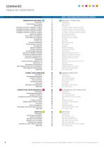
SOMMAIRE TABLE OF CONTENTS CHAPITRE 1 : CONNECTEURS SIM VERSION ÉLECTRIQUE PART 1: SIM CONNECTORS ELECTRICAL VERSION SIM SERIE II CONNECTORS Présentation Caractéristiques techniques Nomenclature Synoptique connecteur métallique 4 modules Synoptique connecteur métallique 2 modules Synoptique connecteur composite 4 modules Synoptique connecteur composite 2 modules Système de référence Fiches clicker nut métalliques Fiches clicker nut composites Accouplement Fiches de rack Fiches de rack inversées Plan de perçage du panneau Accouplement Embases métalliques Embases composites Plan de perçage du panneau...
Open the catalog to page 2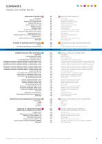
| MODULES AND CONTACTS Presentation Part numbering system Modules for crimped contacts Modules RJ45 Ethernet Gigabit modules / Arinc 800 Grounding modules Shunt modules Crimped contacts (copper cables) Sealing plugs and dummy contacts PCB contacts Front removable PCB contacts PCB layout Modules with wire wrap contacts Part number table | PLATES AND CUSTOM DESIGN CONNECTORS Plates Custom design connectors and connectorization Modules pour contacts a sertir 85 Modules Gigabit / Arinc 800 90 Contacts a sertir (cables cuivre) 93 Obturateurs d'etancheite et faux contacts 94 Contacts a piquer sur C.I....
Open the catalog to page 3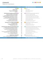
CHAPITRE 3 : OUTILS ET PROCEDURES PART 3: TOOLS AND INSTRUCTIONS TOOLS Tools for contacts Tools for modules Tools for SIM serie II connectors Tools for 1900SIM connectors Part number table | INSTRUCTIONS FOR SIM II SERIES CONNECTOR Instructions for nut polarizing mounting Instructions for key polarizing mounting Instructions for modules insertion in the connector Instructions for MPO modules insertion in the connector Instructions for RJ45 modules insertion in the connector Instructions for modules extraction from the connector Instructions for MPO modules extraction from the connector Backshell...
Open the catalog to page 4
SIM connectors electrical version / Connecteurs SIM version électrique SIM connectors electrical version Connecteurs SIM version électrique
Open the catalog to page 5
AMPHENOL AIR LB - 2 rue Clément Ader, Zac de Wé - 08110 CARIGNAN - FRANCE - Tel. : +33 (0)3 24 22 78 49 - www.amphenol-airlb.fr
Open the catalog to page 6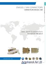
SIM SERIE II CONNECTORS / CONNECTEURS SIM SÉRIE II
Open the catalog to page 7
SIM SERIE II CONNECTORS / CONNECTEURS SIM SÉRIE II PRÉSENTATION PRESENTATION LE CONNECTEUR SIM Le SIM (Système d’Interconnexion Modulaire) Amphenol Air LB est un connecteur Modulaire, Rectangulaire, Multi-contacts, et Multifonctions. Il est disponible en version métallique ou composite, durci ou non, et qualifié selon la norme EN 4165. The Amphenol Air LB SIM (Modular Interconnection System) is a Modular, Rectangular, Multicontact, and Multifunctional connector. It’s available in metallic or composite versions, shielded or not, and qualified according to the EN 4165 spec. Il est constitué d’embases...
Open the catalog to page 8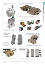
Connecteur SIM Composite protection Cadmium Vert Olive, équipé de capots arrières et de 4 modules Haute Densité taille 23 SIM SERIE II CONNECTORS / CONNECTEURS SIM SÉRIE II Vue éclatée d’un connecteur SIM Composite protection Nickel avec boîtier 2 modules et accessoires arrières Composite SIM Connector with Olive Drab Cadmium plating, equiped with rear accessories and 4 High Density modules size 23 Exploded view of Composite SIM connector, with Nickel Plating, shell size for 2 modules and rear accessories Connecteur SIM Métallique protection Nickel, boîtiers 4 modules, composé d’une fiche de...
Open the catalog to page 9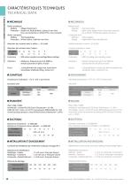
SIM SERIE II CONNECTORS / CONNECTEURS SIM SERIE II W MECANIQUE BoTtier metallique Matiere : Alliage d'aluminium Protection : Nickel noir, Nickel brillant, Cadmium vert olive Pour une protection en Nickel PTFE, nous consulter BoTtier composite Matiere : Thermoplastique Protection : Nickel brillant, Cadmium vert olive Retention des modules dans le boTtier : > 25,4 daN Retention des contacts dans l'isolant : # Contacts 23 22 20 16 12 8 Endurance : 500 cycles complets verrouillage/deverrouillage Vibrations : Aleatoires, frequences de 10 a 2000 Hz, densite spectrale 0,4 g2/Hz, 8 h/axe Chocs : 1 choc/direction...
Open the catalog to page 10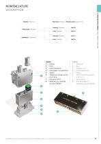
Matiere / Material METALLIQUE / METALLIC COMPOSITE / COMPOSITE Protection / Plating Standard / Standard Durci / Shielded Standard / Standard Durci / Shielded SIM SERIE II CONNECTORS / CONNECTEURS SIM SERIE II 6 - Position du reperage module 8 - Bande RFI pour continuite 6 - Module polarization position AMPHENOL AIR LB - 2 rue Clement Ader, Zac de We - 08110 CARIGNAN - FRANCE - Tel. : +33 (0)3 24 22 78 49 - www.amphenol-airlb.fr
Open the catalog to page 11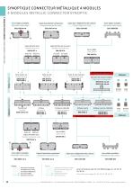
■ SYNOPTIQUE CONNECTEUR METALLIQUE 4 MODULES 4 MODULES METALLIC CONNECTOR SYNOPTIC Serre-cables orientable Adjustable cable clamps Capot de fiche durci Shielded plug cover SIM AD 67 * v i -Fiche clicker nut Clicker nut plug SIM 2N 80 * SIM 2D 80 * -$— Prise de test Test shell 3350 5224 Capot de fiche de rack durci Shielded rack plug cover SIM AD 68 Fiche de rack Rack plug SIM 2N 88 * SIM 2D 88 * ~~v a 5 a~ Fiche de rack inversee Reversed rack plug SIM 2N 89 * SIM 2D 89 Serre-cables Cable clamps SIM AN 60 femelle male female male Embase a collerette Flanged receptacle SIM 2N 84 * SIM 2D 84 Embase...
Open the catalog to page 12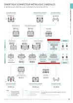
Capot de fiche durci Shielded plug cover SIM AD 37 * Capot de fiche de rack durci Shielded rack plug cover SIM AD 38 Serre-cables Cable clamps SIM AN 30 * SIM SERIE II CONNECTORS / CONNECTEURS SIM SERIE II PAS D'ACCESSOIRE ARRiERE / Bouchon de vol pour embase Flight Cap for Receptacle SIM 2N 32**** SIM 2D 32 Prise de test Test shell 3350 5222 Embase a collerette Flanged receptacle SIM 2N 44 * SIM 2D 44 Embase courte Short receptacle SIM 2N 43 Embase courte a collerette Short Flanged receptacle SIM 2N 45 * SIM 2D 45 femelle male female male & m Hi male femelle male female Modules Capot d'embase...
Open the catalog to page 13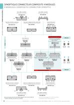
SIM SERIE II CONNECTORS / CONNECTEURS SIM SÉRIE II SYNOPTIQUE CONNECTEUR COMPOSITE 4 MODULES 4 MODULES COMPOSITE CONNECTOR SYNOPTIC Serre-câbles orientable Adjustable cable clamps Serre-câbles monobloc Monoblock cable clamps 3351 6084 303 Capot pour réalignement des contacts bus Contacts alignment cover for bus contacts 3351 6104 303 Capot de protection composants Component protection cover 3351 6014 *** Capot de fiche durci Shielded plug cover 3351 6064 *** Pas d’Accessoire Arrière / No Rear Accessory Bouchon de vol métallique pour embase (2) Metallic flight cap for receptacle SIM 2N 34 ****...
Open the catalog to page 14All Amphenol catalogs and technical brochures
 Connecteurs ASR
28 Pages
 Railway Industry
132 Pages
 1900 connectors
52 Pages
 Push Pull connectors
96 Pages
- Aircraft connector
- Data connector
- Board connector
- Coaxial connector
- Crimp connector
- Electrical power supply connector
- Lightweight connector
- Quadrax connector
- RF connector
- Modular connector
- ARINC connector
- Compact connector
- Custom connector
- Push-pull connector
- Hybrid connector
- Locking connector
- High-performance connector
- Rapid connector