- Catalogs
- Airframes Alaska
- PA-18 LANDING GEAR
PA-18 LANDING GEAR
1 /4Pages

PA-18 LANDING GEAR
1 /4Pages
Catalog excerpts

Section II Paragraphs 2-75 to 2-83 procedure. Adjust the aileron stops (24, figure 2-14) until the clearance between stop bolts and torque tube aileron arm is 3/32-inch when ailerons have reached the limits of their travel. Check that control cables are properly adjusted. Tight cables make stick action stiff while loose cables result in stick action that is too free and uncertain. Properly adjusted cables should not slap or wobble when stick is moved back and forth in rapid succession. NOTE Do not draw turnbuckles tightly against the horns; turnbuckles should move freely over the horns in all positions. When adjusting turnbuckles, not more than two threads should be visible at each end of turnbuckle barrel. Turnbuckles must be safety-wired with 0.040 brass safety wire. 2-76. F LA PS. Position flap control arm so that flaps are in “UP” position. Adjust turnbuckles on flap control cable (5) until flap trailing edges line up with the wing trailing edge. Move flap control arms to “DOWN” position and similarly adjust the flaps until their undersurfaces make an angle of 50 degrees with the undersurface of the wing. Recheck flap trailing edge position when flaps are up. NOTE When adjusting turnbuckies, not more than two threads should be visible at each end of turn-buckle barrel. Turnbuckles must be safety-wired with 0.040 brass safety wire. 2-77. FIN. Plumb the fin at the rudder hinges and make any necessary adjustments. 2-78. RUDDER. Check that the rudder is centered when rudder pedals are in neutral position and that full rudder travel to the left and right is obtainable. Make all adjustments on control cable turnbuckles at rudder horn. Make certain that not more than two threads are visible at each end of turnbuckle barrel and safety-wire the assembly. Plumb the fin at the rudder hinges. 2-79. STABILIZER. Level the stabilizer laterally at the rear spars. The tolerance is plus or minus 1/2 degree. Check that the stabilizer travel is 2 degrees 31 minutes UP and 4 degrees plus or minus 30 minutes DOWN from the neutral position. NOTE (Level airplane, see figure 2-21.) The tension of the tail brace wires will be adjusted to obtain 7/16 inch plus or minus 1/16 inch deflection when a load of 10 pounds plus or minus 1 pound is applied at right angles at the center of the wire. The rear spar of die stabilizer will be level and the elevator hinge line straight. The fin will be vertical at the rudder hinge center line. 2-80. ELEVATORS. Check that the elevators are in neutral position when the control sticks are in neutral. Check that full elevator travel is realized. 2-ar MAIN LANDING GEAR. 2-82. DESCRIPTION. (See figure 2-22.) The main landing gear incorporates individually sprung wheels mounting low pressure 8.00x4 tires. The landing gear vee is hinged at the fuselage and the axles are welded directly to the lower ends of the vee. The shock absorbing struts consist of steel tubes incorporating shock absorbing hydraulic units and rubber shock cord rings. The hydraulic brake system brakes each wheel individually for easy ground maneuvering. Heel-!ype brake pedals are mounted on each side of the cockpit. The rear set of brake pedals are directly connected to the master cylinders and the front pedals are connected to the rear pedals by means of wire tire rods. The right front-and-rear pedals are connected to the right master cylinder actuating the ri?,ht wheel brake and the left set of pedals are connected to the master cylinder actuating the left wheel brake. Parking brake control rods are provided for handlocking the brakes. In order to set the parking brake, pullback on the parking brake control rods (42, figure 2-23). 2-83. REMOVAL OF MAIN LANDING GEAR. (See figure 2-22.) a. Place the fuselage on a padded horse of sufficient height so that the main landing wheels clear the ground. The horse should contact the fuselage at a point just behind the rear landing gear fittings. 1. Landing gear cabane vee 15. 8. Shock cord cover end plate 22. Bolt, nut, cotter pin and washer Bolt, nut, cotter pin and washer LH and RH covered landing gear vee LH and RH landing gear vee Brake line Bolt Bolt, washer, nut and cotter pin Bushing Hub cap Screw Tire and tube Wheel Cotter pin Axle nut Legend for Figure 2-22.
Open the catalog to page 1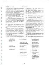
b. Disconnect the LH and RH brake line assemblies (19, figure 2-22) at the fuselage, c. Remove bolt, washer, and nut (2, figure 2-22), bolt (20), bolt, washer, nut and cotter pin (21), and bushing (22). Roll the main landing gear away from the airplane for further dismantling work, d. Remove bolts, nuts, cotter pins, and washers (15 and 16) and separate shock struts (3 and 14) from the covered landing gear vee (17). Disassemble the shock strut assemblies according to figure 2-22. 2-84. CLEANING OF MAIN LANDING GEAR. (See figure 2-22.) a. Clean all metal parts with a cloth moistened in dry cleaning...
Open the catalog to page 3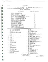
T .0. 1L-21A-2 2-3). During this operation, the wing panel must be root. Refer to the Table III for the proper torq supported at both the outboard portion and at the wing values. TABLE HI. TORQUE VALUES Torque Value (foot-pounds) Wing root rear hinge bolt (L & R) 5-6 Wing root front hinge bolt (L & R) 6-7 Front lift strut to spar fitting (L & R) 1 bolt 3-5 Rear lift strut to spar fitting (L Si R) 1 bolt 3-5 Front and rear lift strut to fuselage bolts (L & R) 2 bolts 3 Elevator upper connector link (upper bolt) 1 Elevator upper connector link (lower bolt) 5...
Open the catalog to page 4All Airframes Alaska catalogs and technical brochures
 ABI 3450-23
2 Pages
 ABI 3400B
2 Pages
 vABI 3400TWFK
2 Pages
 SINGLE SHOCK T3
8 Pages