US-D1

US-D1
Ainstein's UAV Standard Radar Altimeter US-D1 is a compact and highly customizable radar altimeter designed for UAVs. It is suitable for various environments, including mountainous terrains and over water bodies, and meets IP67 standards for dust and water protection, ensuring durability and performance in challenging conditions.
Specifications
The US-D1 operates at a frequency band of 24 GHz with a bandwidth of 190 MHz. It has a minimum operating altitude of 0.5 meters and a maximum of 50 meters, with altitude precision of 6.0 cm for altitudes less than 1 meter and 4.0 cm for altitudes greater than 1 meter. The device supports UART and CAN interfaces with update rates of 82 Hz and 86 Hz, respectively. It operates within a temperature range of -20 °C to 65 °C and consumes 2W of power at 5 Volts DC input.
Technical Features
The radar is designed to be robust at high speeds and turbulence, with a single board electronics design. It is compact, fitting in the palm of a hand, and is easy to use with plug-and-play capabilities and firmware upgrades via CAN/UART.
Data Protocols
The US-D1 supports both UART and CAN data protocols. The UART protocol has a baud rate of 115200 b/s, while the CAN protocol supports a baud rate of 1 Mb/s. Data packets for both protocols are defined, with specific structures for altitude and signal-to-noise ratio (SNR) data.
Installation Instructions
The radar should be mounted with its face perpendicular to the target and kept clean. It should not be obstructed by mechanical landing gear, and unexpected objects should be kept out of its field of view.
Known Issues
Several known issues include inconsistent readings outside the maximum operational altitude, potential errors in indoor environments due to multipath reflections, and risks associated with incorrect power supply connections to the CAN bus.
About Ainstein
Ainstein focuses on enhancing safety through radar-based technology, offering solutions for autonomous drones and vehicles. The company is recognized for its innovation in radar systems, including the development of the world's first UAV collision avoidance radar with 4D detection. Ainstein's products are customizable, precise, and cost-effective compared to competitors.
Catalog excerpts

US-D1 UAV Radar Small. Easy Setup. Highly Customizable. Safety from numbers
Open the catalog to page 1
ADDRESS: 2029 Becker Drive, Lawrence, KS 66047 USA EMAIL: [email protected] PHONE: 785-856-0460
Open the catalog to page 2
instein’s UAV Standard Radar Altimeter US-D1 is still the most compact radar altimeter for UAVs on the market today. So small it fits in the palm of your hands, you'll have greater flexibility with precious onboard real estate and payload. The Standard Radar Altimeter US-D1 is designed to work in a multitude of environments from mountainous terrain to tree canopies, sand and water. Do you fly over lakes or the ocean? It’s normal for your UAV’s components to get wet from choppy water, or simply from rain or fog. Worried about your expensive UAV electronics getting coated in mist from agricultural...
Open the catalog to page 3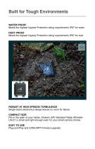
Built for Tough Environments WATER PROOF Meets the highest Ingress Protection rating requirements IP67 for water DUST PROOF Meets the highest Ingress Protection rating requirements IP67 for dust ROBUST AT HIGH SPEEDS/ TURBULENCE Single board electronics design leaves no room for failure COMPACT SIZE Fits in the palm of your hands, Ainstein UAV Standard Radar Altimeter US-D1 is small and light enough even for your small camera drones EASY TO USE Plug-and-Play and CAN/UART firmwar
Open the catalog to page 4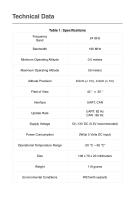
Technical Data Table 1: Specifications Frequency Band Minimum Operating Altitude Maximum Operating Altitude Altitude Precision Update Rate Supply Voltage Power Consumption Operational Temperature Range Environmental Conditions
Open the catalog to page 5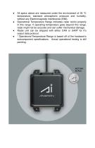
All specs above are measured under the environment of 35 °C temperature, standard atmospheric pressure and humidity, without any Electromagnetic Interference (EMI). Operational Temperature Range indicates radar works properly in this range. If operating temperature goes beyond this range, radar might not be accurate and can suffer mechanical damage. Radar unit can be shipped with either CAN or UART for it’s output data protocol. * Operational Temperature Range is based off of the hardware’s subcomponent specifications. Actual operational testing is st
Open the catalog to page 6
UART Data Protocol Specifications ● ● ● ● ● Baud Rate: 115200 b/s Data bit: 8 Parity bit: N Stop bit: 1 Voltage Level: 3.3V A single data packet consists of six(6) bytes. Table 2 defines the packet structure. Table 2: UART Data Packet Definition From Packet Head Altitude (Least Significant 8 Bits) Altitude (Most Significant 8 Bits) Checksum (see formula below) Notes: • '*' refers to a variable bit containing dynamic data. • This table ONLY describe the data format of standard firmware version. Please contact Ainstein AI for data formats of any customized firmware versions or customized firmware. requirement....
Open the catalog to page 7
CAN Data Protocol Specifications ● ● ● Baud Rate: 1 Mb/s Frame ID: customized (Standard Frame, Extended Frame) Standard: CAN Protocol 2.0 section A and B, ISO 11898-1:2015,-4 A single data packet uses four bytes of either, a Standard or Extended CAN frame. The type of CAN frame used and CAN ID of the device can be customized. The CAN frame is defined in table 3. Table 3: CAN Frame Data Packet Definition From Extended ID frame (Default 0x00090002) Altitude (Most Significant 8 Bits) Altitude (Least Significant 8 Bits) SNR(Most Significant 8 Bits) SNR(Least Significant 8 Bits)
Open the catalog to page 8
Mechanical Drawing Figure 1: Dimensions of US-D1 (Units: mm) Figure 2: Field of View Orientation
Open the catalog to page 9
Hardware Interface Table 4: Data Packet Definition Wire Color Figure 3: US-D1 Cabling Interface
Open the catalog to page 10
Installation Instructions Mounting Requirements: Radar face should be perpendicular to the target to be measured Keep radar face clean, and do not cover it. Keep any unexpected objects out of radar’s FoV (Field of View), otherwise it might situate radar’s signal No specific requirement for mounting orientation Figure 3: Proper Mounting Example Ensure altimeter will not be obstructed by mechanical landing ge
Open the catalog to page 11
Known Issues Table 5 lists the known issues that will be addressed in future revisions. Table 5: US-D1 Known Issues Issue ID If US-D1 is used outside of its Maximum O p e r a t i o n a l A l t i t u d e ( Ta b l e 1 ) . Inconsistent small readings will be output(See Figure 4 below). ● For full confidence, only consider US-D1’s data when used within its operating range Altitude data from US-D1 may have various step-size, since some postprocessing algorithm is implemented after radar processing, e.g. averaging, filtering. Altitude data from US-D1 may give unexpected or incorrect measurements under...
Open the catalog to page 12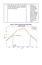
The CAN Bus that CAN HI and CAN LOW are connected to must be between -2V and 5V power supply or it is at risk of burning the hardware. ● Under no circumstances will Ainstein be held responsible or liable in any way for any claims, damages, losses, expenses, costs or liabilities whatsoever from your use of the US-D1 outside the range a -2V and 5V power supply Figure 5: US-D1 Altitude Drop-off Example
Open the catalog to page 13
Hardware & Firmware Version Firmware
Open the catalog to page 14
About Ainstein Our mission is to enable safer driving, flying, working and living through radarbased technology. We are in the business of improving safety and protecting valuable assets through innovations in radar technology. Ainstein makes radar systems smarter, more affordable and easier to deploy. We offer complete solutions for autonomous drones, advanced driver-assistance systems (ADAS), autonomous vehicles and industrial sensing – incorporating a combination of millimeter wave (mmWave) radar, sensor fusion and artificial intelligence (AI). For years, cost, weight and performance constraints...
Open the catalog to page 15

