Catalog excerpts

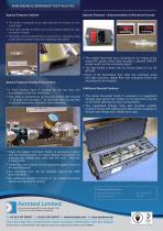
AERO ENGINE & COMPONENT TEST FACILITIES Aerotest Limited Consultants & Specialists in Aero Engine Test Facilities & Ground Support Equipment A small flow control needle valve is mounted in line with the low flow flowmeter. Suitable flowmeter straighteners are provided upstream and downstream, at either end of each flowmeter straightener there are self-sealing quick disconnect couplings to allow for easy interfacing with the customer’s hydraulic facility hose/ pipework connections. Two high accuracy digital flow rate indicators are mounted into the chassis, each corresponding to one of the flowmeters. ATL 1310-001 Hydraulic or or Fuel Master Flowmeter Facility To operate, the facility must be connected to a suitable local mains electrical supply. A fused IEC socket which also includes a rocking isolator switch is located on the top of the facility. The compact, portable, user friendly and cost effective master flowmeter facility has been designed to check, in situ, whether Part Marking flowmeters that are currently in service on a facility are within OEM tolerance. The master flowmeter facility is individually identified with the following information: The flow ranges of the master flowmeter facility make it suitable for various hydraulic and fuel facilities using mineral hydraulic oil or fuel. • Part Number The master flowmeter facility consists of a 700mm Long, 300mm • Description Wide and 120mm Deep Stainless Steel chassis with a removable access panel on the rear. • |ndividual Serial number Two flowmeters are mounted onto this chassis; one for high flowrates (19-190 LPM/ 2.19 - 41.79 GPM UK) and one for low flowrates (0.2-19 LPM/ 0.043 - 2.19 GPM UK) as a typical flow rate range, although the flowmeter flow ranges can be changed in order to suit different applications. • Complete Operating and Maintenance instructions are supplied with each facility. The benefits of the Aerotest hydraulic or fuel master flowmeter facility include: • Complete Stainless Steel construction • The facility design allows for quick installation and removal, saving valuable operator time. • Aerotest design provides simplicity and can be calibrated to check either hydraulic or fuel facility flowmeters. • The master flowmeter rig can be installed either upstream or downstream of the test flowmeter. • The facility OEM flowmeter tolerance can be quickly established on site without the need for the end user sending the flowmeters off to third parties for verification. • The facility is supplied as a complete kit of parts.
Open the catalog to page 1
AERO ENGINE & COMPONENT TEST FACILITIES • The facility is designed to be used lying flat on its back on four rubber feet. • Flush ABS handles at either end of the chassis enable the user to position it easily. • The facility can be checked that it is level prior to operating using a spirit level mounted on the front stainless steel panel. • The master flowmeter rig is switched on by means of the fused IEC socket which also includes a latched ON/OFF rocker switch on the top facility panel. • The Test Facility is fitted with 2m Power Cable C13 to UK BS1363. • Each of the flowmeters flow rates...
Open the catalog to page 2All AEROTEST LIMITED catalogs and technical brochures
-
Environmentally Protective
2 Pages
-
Alison T56-A14/A15
2 Pages


